
Cutting type multi-angle adjusting separating forceps for laparoscopic surgery

A surgical, multi-angle technology, applied in the direction of laparoscopy, surgical forceps, application, etc., can solve problems such as organ separation and other operations are limited, and the clamping part of the separation forceps cannot be adjusted in direction.

Pending Publication Date: 2022-01-28
岳阳职业技术学院
View PDF0 Cites 0 Cited by
  • Summary
  • Abstract
  • Description
  • Claims
  • Application Information

AI Technical Summary

Problems solved by technology

[0004] The technical problem to be solved by the present invention is: the clamping part of the existing separation forceps cannot adjust the direction, resulting in more restrictions on the separation of organs during the surgical operation, so that laparoscopic surgery requires the use of right-angled forceps, etc. Various other instruments are required to complete the operation

Method used


Image

  • Cutting type multi-angle adjusting separating forceps for laparoscopic surgery
  • Cutting type multi-angle adjusting separating forceps for laparoscopic surgery
  • Cutting type multi-angle adjusting separating forceps for laparoscopic surgery

Examples


Embodiment 1

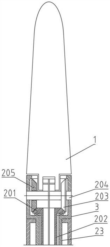
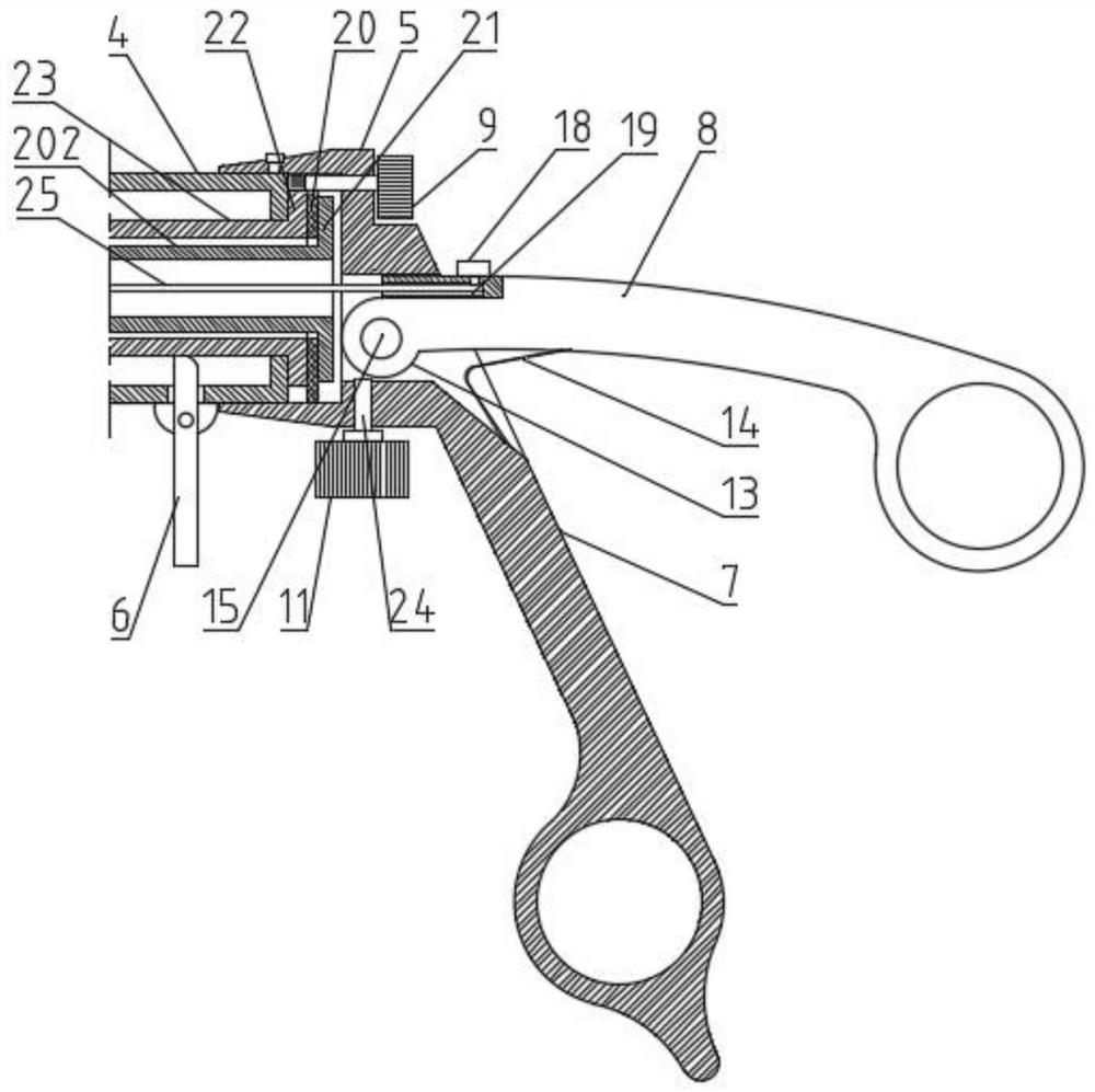
[0052] Such as Figure 1-11 As shown, a scissors type laparoscopic surgery with multi-angle adjustment separation forceps, comprising a rod body 4, the front end of the rod body 4 is provided with a swivel seat 3, the swivel seat 3 is provided with a turning mechanism 2; the turning mechanism 2 A clamping part 1 is arranged on it; the tail end of the rod body 4 is connected to an end seat 5; a first joystick 7 and a second joystick 8 for controlling the opening and closing of the clamping part 1 are arranged on the end seat 5; The end surface of the end seat 5 is provided with a rotary knob 9 for controlling the rotation of the rotary seat 3 and a turning knob 10 for controlling the flipping of the clamping part 1; the tail end of the rotary seat 3 is connected to a rotary rod 23; the rotary rod 23 passes through The rod body 4 is connected with the second toothed disc 22 behind; the pinion 17 coaxially connected with the rotary knob 9 meshes with the second toothed disc 22; t...

Embodiment 2

[0055] Such as image 3 As shown, as a further optimization of the above embodiment: the front end of the second joystick 8 is provided with a turntable body 13; the turntable body 13 is provided with an installation hole, and the installation hole is sleeved on the installation shaft 15 of the first joystick 7 ; The end seat 5 is provided with a positioning knob 11 ; The turntable body 13 and the second joystick 8 are of an integrated structure, and the mounting holes are coaxially arranged on the turntable body 13; the outer wall of the turntable body 13 can be provided with a non-slip surface; the positioning knob 11 is connected to the screw rod 24, and when the positioning knob 11 is rotated, The screw rod 24 can bear against the turntable body 13, thereby preventing the second joystick 8 from swinging.

Embodiment 3

[0057] Such as image 3 As shown, as a further optimization of the above embodiment: the side of the rod body 4 is connected to the control rod 6 through a hinge shaft, and the front end of the control rod 6 extends into the rod body 4 to withstand the rotating rod 23 . The control rod 6 is short rod-shaped, and the hinge shaft is arranged at the upper end position of the middle section of the control rod 6; anti-slip lines can be set on the outer wall of the rotating rod 23, and the upper end of the control rod 6 is against the anti-slip lines, thereby preventing the rotating rod 23 from rotate. The anti-slip texture can adopt toothed texture.


PUM


Abstract

The invention relates to the technical field of laparoscopic surgical instruments, in particular to a pair of cutting type multi-angle adjusting separating forceps for laparoscopic surgery. A turnover mechanism is arranged in a rotating seat at a front end of a rod body; a clamping part is arranged on the turnover mechanism; a rotating rod at the tail end of the rotating seat is connected with a second fluted disc; a driven bevel gear on a rotating shaft of the turnover mechanism is meshed with the driving bevel gear; the driving bevel gear is connected with a driving rod; the driving rod is connected with a first fluted disc; and the clamping part is connected with the second operating rod through a pull wire. The pair of separating forceps has the beneficial effects that the direction of the separating forceps can be freely adjusted in a semispherical surface when the separating forceps face a narrow operation area in an operation process; the problems that in the laparoscopic surgery, due to the fact that the direction of the separating forceps clamping part cannot be adjusted when the separating forceps clamping part clamps and separates human tissue in the surgery, an operator excessively swings when operating a rod body with force, an external incision of the surgery is enlarged, and normal tissue in the incision is damaged are solved, the non-surgical injury risk is effectively reduced, and meanwhile, the efficiency and the safety of the laparoscopic surgery are also improved.

Description

technical field [0001] The invention relates to the technical field of medical instruments for laparoscopic surgery, in particular to a scissor-hold type multi-angle adjustable separation forceps for laparoscopic surgery. Background technique [0002] Laparoscopic surgery refers to making several small incisions in different parts of the abdomen, inserting camera lenses and various special surgical instruments through these small incisions, and transmitting the images of various organs in the abdominal cavity captured by the cameras inserted into the abdominal cavity to the On the TV screen, the surgeon observes the images and performs operations outside the body with various surgical instruments to complete the operation. [0003] In laparoscopic surgery, one or more incisions are often made on the patient's flesh. Once a lesion is found during the operation, it needs to be removed. During the resection, the internal organs need to be separated to find the lesion. In the pr...

Claims


Application Information

Patent Timeline
Patent Type & Authority Applications(China)
IPC IPC(8): A61B17/29A61B1/313A61B1/04
CPCA61B17/29A61B1/3132A61B1/04A61B2017/2927A61B2017/2947A61B2017/2925A61B2017/2912
Inventor 邹进邹仲华李政林
Owner 岳阳职业技术学院
Learn More