A water distribution system with automatic identification function

A water distribution system and automatic identification technology, applied in mixer accessories, mixers, dissolving and other directions, can solve the problems of troublesome process of adding water and affect work efficiency, and achieve the effect of reducing workload and improving work efficiency.

Active Publication Date: 2022-03-22
SHIJIAZHUANG TIEDAO UNIV
View PDF0 Cites 0 Cited by
  • Summary
  • Abstract
  • Description
  • Claims
  • Application Information

AI Technical Summary

Problems solved by technology

[0002] During the mixing process of some raw materials, water needs to be added. However, the traditional way of adding water is to add water directly or manually, which will make the process of adding water more troublesome and affect work efficiency. Therefore, we propose a Water distribution system with automatic identification function

Method used


Image

  • A water distribution system with automatic identification function
  • A water distribution system with automatic identification function
  • A water distribution system with automatic identification function

Examples


Embodiment 1

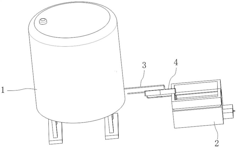
[0037] The invention provides a technical solution: a water distribution system with automatic identification function, please refer to figure 1 , including: a water storage tank 1 and a mixing tank 2;

[0038] A water pump is installed at the bottom of the inner cavity of the water storage tank 1, and the outlet of the water pump is connected to the conduit 3. The top wall of the mixing tank 2 is equipped with a water distribution mechanism 4, and the end of the conduit 3 away from the water pump is connected to the water distribution mechanism 4. The electrical equipment involved in the device Both are electrically connected by wires and external power switches;

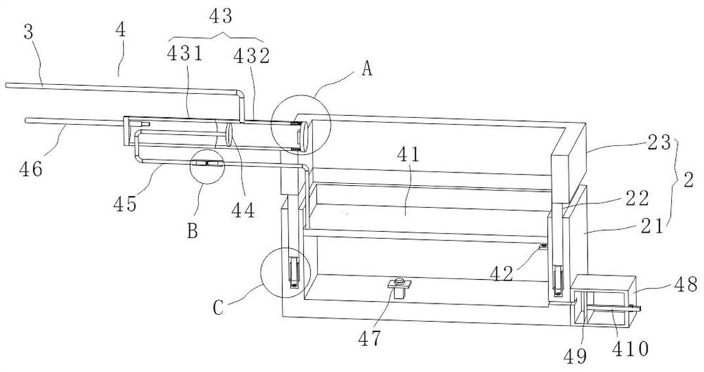
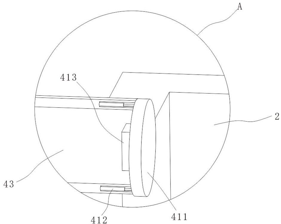
[0039] see figure 2 , the water distribution mechanism 4 includes a supporting plate 41 slidably installed in the inner cavity of the mixing tank 2, the bottom wall of the supporting plate 41 and the bottom of the inner cavity of the mixing tank 2 are filled with air, and the inner wall on the right side of the m...

Embodiment 2

[0046] see figure 2 and Figure 5 , on the basis of Embodiment 1, the mixing pool 2 includes an upper pool body 23 and a lower pool body 21, the top wall of the lower pool body 21 is provided with a mounting groove, and the bottom wall of the upper pool body 23 is equipped with a movable block 22, and the movable block 22 slides into the In the inner cavity of the installation groove, and the bottom of the inner cavity of the installation groove is equipped with an installation sleeve 5, the top of the installation sleeve 5 inner cavity is slidingly inserted with a push rod 6, the top of the push rod 6 is connected with the bottom wall of the movable block 22, and the push rod 6 A magnetic block is installed at the bottom, an electromagnet 7 is installed at the bottom of the inner cavity of the installation sleeve 5, and a push switch 47 is installed at the bottom of the inner cavity of the lower pool body 21, and the push switch 47 is electrically connected with the electrom...

Embodiment 3

[0050] In order to enhance the practicability of the equipment of this application, expand its functions, and enhance the mixing efficiency of water and raw materials, the embodiment of this application adds an auxiliary mixing component 8 on the basis of the above-mentioned embodiments, and uses gas to accelerate the mixing process by accumulating and releasing elastic potential energy. The mixing of raw materials and water on the supporting plate 41; specifically:

[0051] Such as Figure 6 to Figure 16 As shown, the auxiliary mixing assembly 8 includes an air storage air bag assembly 81 and an air injection restriction assembly 82; the air storage air bag assembly 81 is located under the support plate 41, and its main body is an air bag structure for storing gas; The air injection restriction assembly 82 is used to limit the output of the gas in the air storage airbag assembly 81, and acts as a valve body; in actual use, the air storage airbag assembly 81 injects air into t...


PUM


Abstract

The present application discloses a water distribution system with automatic identification function, comprising: a water storage tank and a mixing tank, a water pump is installed at the bottom of the inner cavity of the water storage tank, and the outlet of the water pump is connected to a conduit, and the top wall of the mixing tank is installed with The water distribution mechanism, the end of the conduit away from the water pump is connected to the water distribution mechanism. In the device, the raw materials are added to the mixing tank, so that the raw materials fall on the top of the supporting plate, and the supporting plate will move down under pressure, and the touch switch will be pressed to make the The water pump works and injects the water in the water storage tank into the inner cavity of the water injection pipe. The water will fill the space between the baffle plate and the cover plate, squeeze the air bag, press the switch, and the electric telescopic rod will be energized to work. Move the cover plate to the right to open the right side of the water injection pipe, add water to the mixing tank, and inject water into the raw materials for mixing raw materials, so as to realize automatic identification and automatic water distribution, reduce the workload of the staff, and improve work efficiency.

Description

technical field [0001] The invention relates to the technical field of water distribution equipment, in particular to a water distribution system with an automatic identification function. Background technique [0002] During the mixing process of some raw materials, water needs to be added. However, the traditional way of adding water is to add water directly or manually, which will make the process of adding water more troublesome and affect work efficiency. Therefore, we propose a Water distribution system with automatic identification function. Contents of the invention [0003] The purpose of the present invention is to provide a water distribution system with an automatic identification function to solve the problems raised in the above-mentioned background technology. [0004] To achieve the above object, the present invention provides the following technical solutions: [0005] A water distribution system with automatic identification function, comprising: [00...

Claims


Application Information

Patent Timeline
Patent Type & Authority Patents(China)
IPC IPC(8): B01F35/71
Inventor 施颖颖
Owner SHIJIAZHUANG TIEDAO UNIV
Why Eureka
Try Eureka