
Bending device for screw gasket

A technology of bending device and screw, which is applied in the direction of feeding device, positioning device, storage device, etc., and can solve the problems of hitting workers' safety hazards, screws and gaskets flying away, etc.

Pending Publication Date: 2022-01-28
NINGBO XUEBOTE FASTENER
View PDF0 Cites 0 Cited by
  • Summary
  • Abstract
  • Description
  • Claims
  • Application Information

AI Technical Summary

Problems solved by technology

[0003] In view of the above problems, the present invention proposes a bending device for screw gaskets, which solves the problem of the screws and gaskets flying off during the bending process of the screw gaskets in the existing bending device for screw gaskets , which may hit the worker's safety hazard flaws

Method used


Image

  • Bending device for screw gasket
  • Bending device for screw gasket
  • Bending device for screw gasket

Examples


Embodiment 1

[0037] The technical solutions taken by the present invention are as follows:

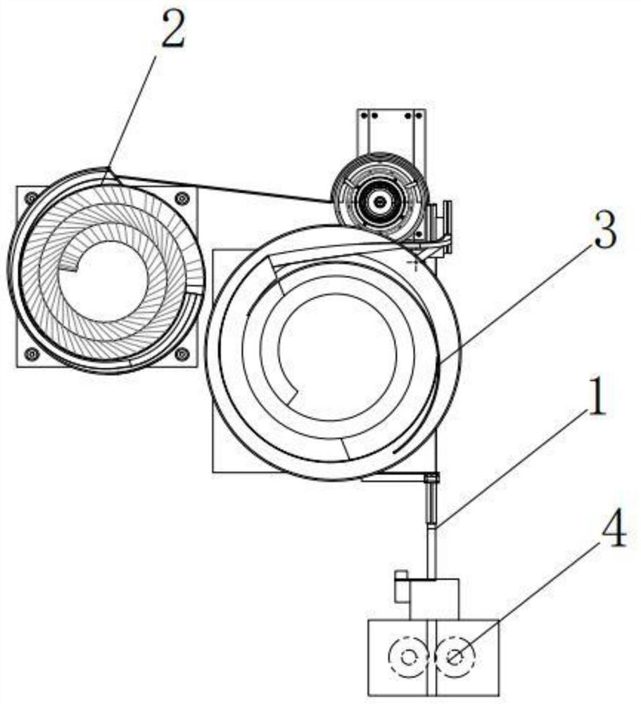
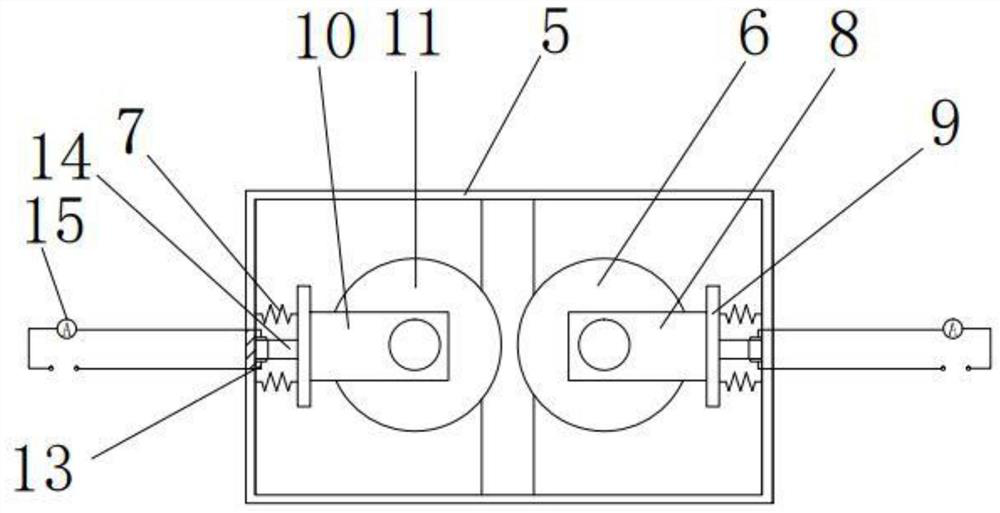
[0038] like figure 1 and figure 2 , The present invention also discloses a gasket screw press bending apparatus, comprising: a transport rail 1, the feed screw oscillating assembly 2, the gasket 3 and the feed screw shim assembly vibration bending assembly 4; the screw vibration feed assembly located at the front end of the conveying path; said vibration feed assembly pad connected to the feed screw located in the rear end of the conveying track assembly vibration; bending the spacer screw assembly connected to the end of the conveying path; wherein said screw press brake pad assembly includes a cartridge 5, the cartridge body 6 is provided with a pair of squeezing structure, the pair of side walls respectively connecting extruded structure of a first spring cassette 7; the extruded structure comprises a holder 8 said holder comprising a bottom plate 9 and a pair of side plates connecting the bottom pl...

Embodiment 2

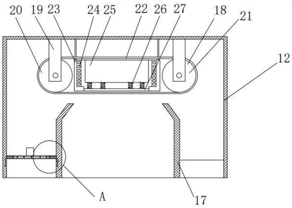
[0041] like image 3 , Figure 4 , Figure 5 , Image 6 , Figure 7 and Figure 8 , The present invention also discloses a gasket screw press bending apparatus, comprising: a transport rail, the feed screw vibration assembly, the gasket assembly and the feed screw washer bending vibration assembly; said vibration feed screw assembly at the front end of the conveying path; said vibration feed assembly pad connected to the feed screw located in the rear end of the conveying track assembly vibration; bending the spacer screw assembly connected to the end of the conveying path; wherein the spacer screw press bending assembly includes a cartridge body, the cartridge body is provided with a pair of squeezing structure, a pair of side walls connected by extruded structure are cartridge spring; said extruded structure comprises a holder, said holder comprising a base plate and a connection plate a pair of side plates, the wheel is mounted between the pair of side plates; top of the box body is ...


PUM


Abstract

The invention discloses a bending device for a screw gasket. The bending device comprises a conveying rail, a screw feeding vibration assembly, a gasket feeding vibration assembly and a screw gasket bending assembly; the screw feeding vibration assembly is located at the front end of the conveying rail; the gasket feeding vibration assembly is connected to the conveying rail located at the rear end of the screw feeding vibration assembly; the screw gasket bending assembly is connected to the tail end of the conveying rail; the screw gasket bending assembly comprises a box body, a pair of extrusion structures are arranged in the box body, and the pair of extrusion structures are connected with the side wall of the box body through first springs correspondingly; the extrusion structure comprises a fixing frame, the fixing frame comprises a bottom plate and a pair of side plates connected with the bottom plate, and an extrusion wheel is installed between the pair of side plates; and a collection box is arranged on the top of the box body. The invention overcomes the defect that: in the bending process of a screw gasket in an existing screw gasket bending device, the problem that the screw and the gasket bounce away exists, and potential safety hazards of workers are possibly hit.

Description

Technical field [0001] The present invention relates to the field of curved devices of the screw gasket, and more particularly to a rotating device of a screw gasket. Background technique [0002] At present, the existing screw gasket is curved, the main function of the pressing mechanism is to insert the screws that are not fully inserted into the gasket into the gasket; the end point of the conveying track is a tilted track, gasket The screws are slid down from the inclined track, and the squeezed wheel is provided on both sides of the inclined track, and the spacer is slightly bendered slightly under the action of the extrusion wheel on both sides, so that the hole deformation on the gasket will eventually make the gasket not from the screw Ethereal. However, the screw gaskets are in the process of being curved, and there is a problem of screws and gaskets that may hit the safety hazard of workers. Inventive content [0003] In response to the above problems, a rotation devic...

Claims


Application Information

Patent Timeline
Patent Type & Authority Applications(China)
IPC IPC(8): B21D39/00B21D43/00B21D43/12B21D43/20
CPCB21D39/00B21D43/003B21D43/12B21D43/20
Inventor 邱国伟
Owner NINGBO XUEBOTE FASTENER
Learn More