Canopy air tightness test fixture

A technology for testing fixtures and cockpit covers, which is applied in the field of fixture tooling, can solve the problems of scrapping of hatch cover parts, sealing failure, and excessive force on the hatch cover, and achieves the effect of improving sealing performance and ensuring sealing performance.

Active Publication Date: 2022-01-28
辽宁华天航空科技股份有限公司
View PDF6 Cites 2 Cited by
  • Summary
  • Abstract
  • Description
  • Claims
  • Application Information

AI Technical Summary

Problems solved by technology

[0002] In the airtightness test of the existing canopy, the canopy is usually manually positioned and then compressed. Since the canopy requires a circumferential seal, if the canopy is not positioned accurately or the pressing force is uneven, it may cause Sealing failure will seriously affect the test efficiency of the airtightness test of the canopy. At the same time, manual positioning may cause excessive force during the locking process of the canopy, resulting in damage to the canopy, seriously affecting the product quality of the canopy, and even causing the canopy to be damaged. Scrapping of whole parts

Method used


Image

  • Canopy air tightness test fixture
  • Canopy air tightness test fixture
  • Canopy air tightness test fixture

Examples


Embodiment Construction

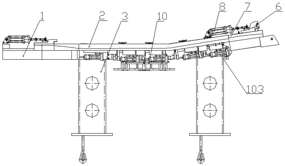
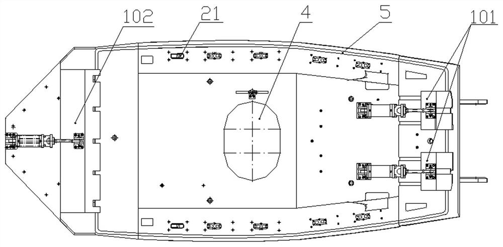
[0019] A canopy air tightness test fixture, the fixture is used to clamp the air tightness test of the canopy of an existing small aircraft, so the description of the overall structure of the fixture adopts the perspective of the aircraft canopy located in the aircraft position. The position of the test fixture where the front end of the aircraft canopy is located is the front end of the test fixture, the position of the test fixture where the rear end of the aircraft canopy is located is the rear end of the test fixture, and the two sides of the aircraft canopy are the two sides of the test fixture.

[0020] like figure 1 and figure 2 As shown in the figure, the specific structure of the canopy air tightness test fixture is as follows: the upper surface of the base 1 of the frame structure is positioned and connected to the airtight platform 2, and the lower surface of the base 1 is respectively provided with uprights 3 before and after; There is a sealing rubber ring 5, an...


PUM


Abstract

The invention relates to a canopy airtightness test fixture, which is characterized in that: an airtight platform is positioned and connected on the upper surface of a base of a frame structure, and upright posts are respectively arranged in front and back of the lower surface of the base; a sealing rubber ring is arranged on the periphery of the airtight platform, and the lower edge of a canopy to be detected and the sealing rubber ring of the airtight platform are pressed, sealed and matched by an external pressure applying device; the external pressure applying device is composed of a front pressing device, a rear pressing device and a side tensioning device; an inspection hole is formed in the middle of the base and communicates with an inner cavity of a canopy to be detected, the bottom of the inspection hole is connected with a shielding cover plate, and the cover plate is in sealed connection with the base through bolts arranged on the circumference; the base is provided with a sealing joint for inflating and a sealing joint for vacuumizing, which communicate with the inner cavity of the canopy to be detected. The canopy air tightness test fixture is uniformly distributed, so that the pressing force is uniform in the automatic locking process, and the sealing performance is improved.

Description

technical field [0001] The invention relates to a cockpit cover air tightness test fixture, which belongs to the technical field of fixture tooling. Background technique [0002] In the air-tightness test of the existing canopy cover, the canopy cover is usually positioned manually and then pressed. Since the hatch cover requires a circumferential seal, if the canopy cover is not positioned accurately or the pressing force is not uniform, it may cause problems. The failure of the seal will seriously affect the test efficiency of the air tightness test of the canopy cover. At the same time, manual positioning may also cause excessive force during the hatch cover locking process, which may cause damage to the hatch cover, seriously affect the product quality of the hatch cover, and even cause the hatch cover to be damaged. Scrap of integral parts. SUMMARY OF THE INVENTION [0003] The technical problem to be solved by the present invention is to provide a canopy air tightne...

Claims


Application Information

Patent Timeline
Patent Type & Authority Applications(China)
IPC IPC(8): B25B11/00G01M3/00
CPCB25B11/00G01M3/00
Inventor 刘旭东姚振东高帅
Owner 辽宁华天航空科技股份有限公司
Why Eureka
Try Eureka