A laser welding method for stainless steel thick-walled pressure vessel

A pressure vessel, laser welding technology, applied in laser welding equipment, household containers, welding equipment and other directions, to ensure welding positioning accuracy, ensure strength and air tightness, and solve the effect of arc crater defects

Active Publication Date: 2018-07-06
HUBEI SANJIANG AEROSPACE GRP HONGYANG ELECTROMECHANICAL
View PDF6 Cites 0 Cited by
  • Summary
  • Abstract
  • Description
  • Claims
  • Application Information

AI Technical Summary

Problems solved by technology

[0003] In view of the above-mentioned problems in the prior art, the main purpose of the present invention is to provide a laser welding method for stainless steel thick-walled pressure vessels, which solves the problem of welding strength of high-strength stainless steel materials in solid solution or age-strengthened state, and the welding strength is high. And stable, realize the equal strength connection of base metal

Method used


Image

  • A laser welding method for stainless steel thick-walled pressure vessel
  • A laser welding method for stainless steel thick-walled pressure vessel
  • A laser welding method for stainless steel thick-walled pressure vessel

Examples


Embodiment 1

[0054] The thick-walled pressure vessel in the embodiment of the present invention includes a tank body, a top cover body, a cover plate, a conduit, and a nozzle. One end of the container is connected to the top cover, and the other end is connected to the cover plate; one end of the conduit is connected to the low-pressure gas outlet of the low-pressure buffer container, and the other end is connected to the nozzle; the tank body is connected to the top The cover is made of solid solution strengthened or aging strengthened stainless steel.

[0055] The processing, assembly and welding forming steps of the thick-walled pressure vessel in the embodiment of the present invention specifically include the following:

[0056] (1) Parts processing steps:

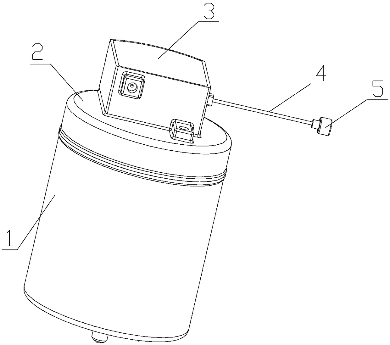
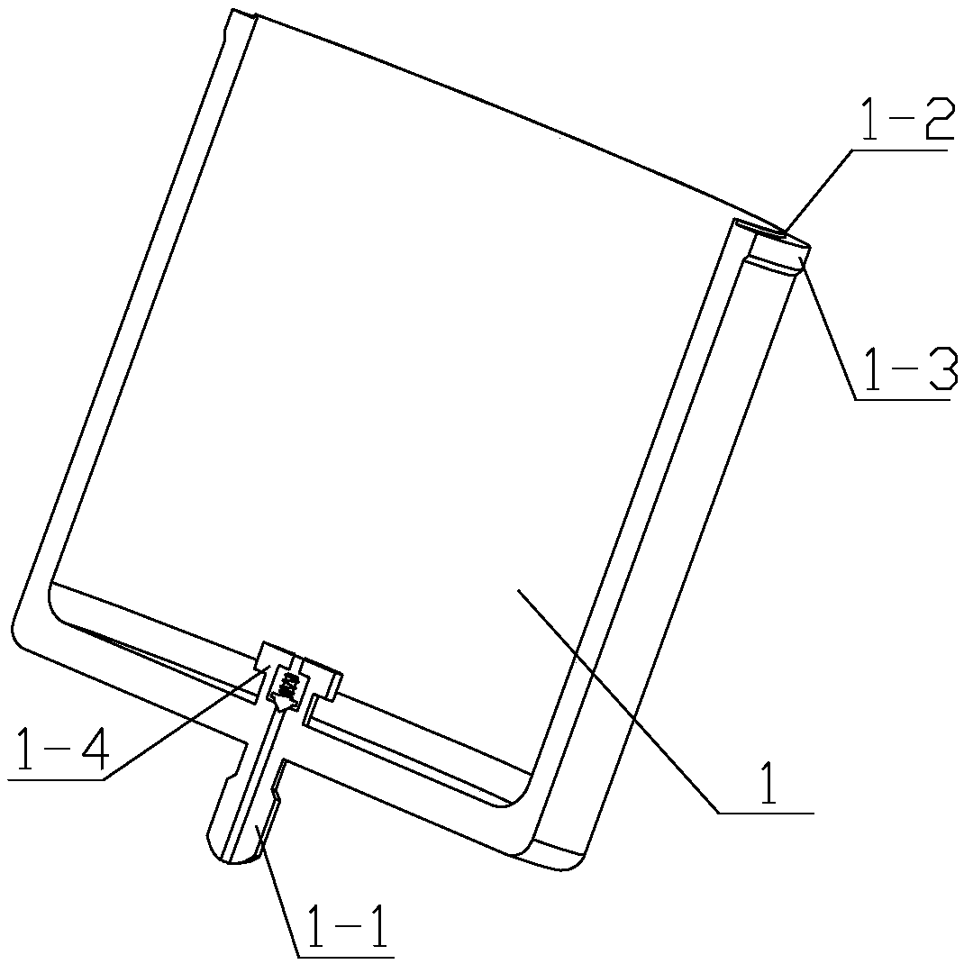
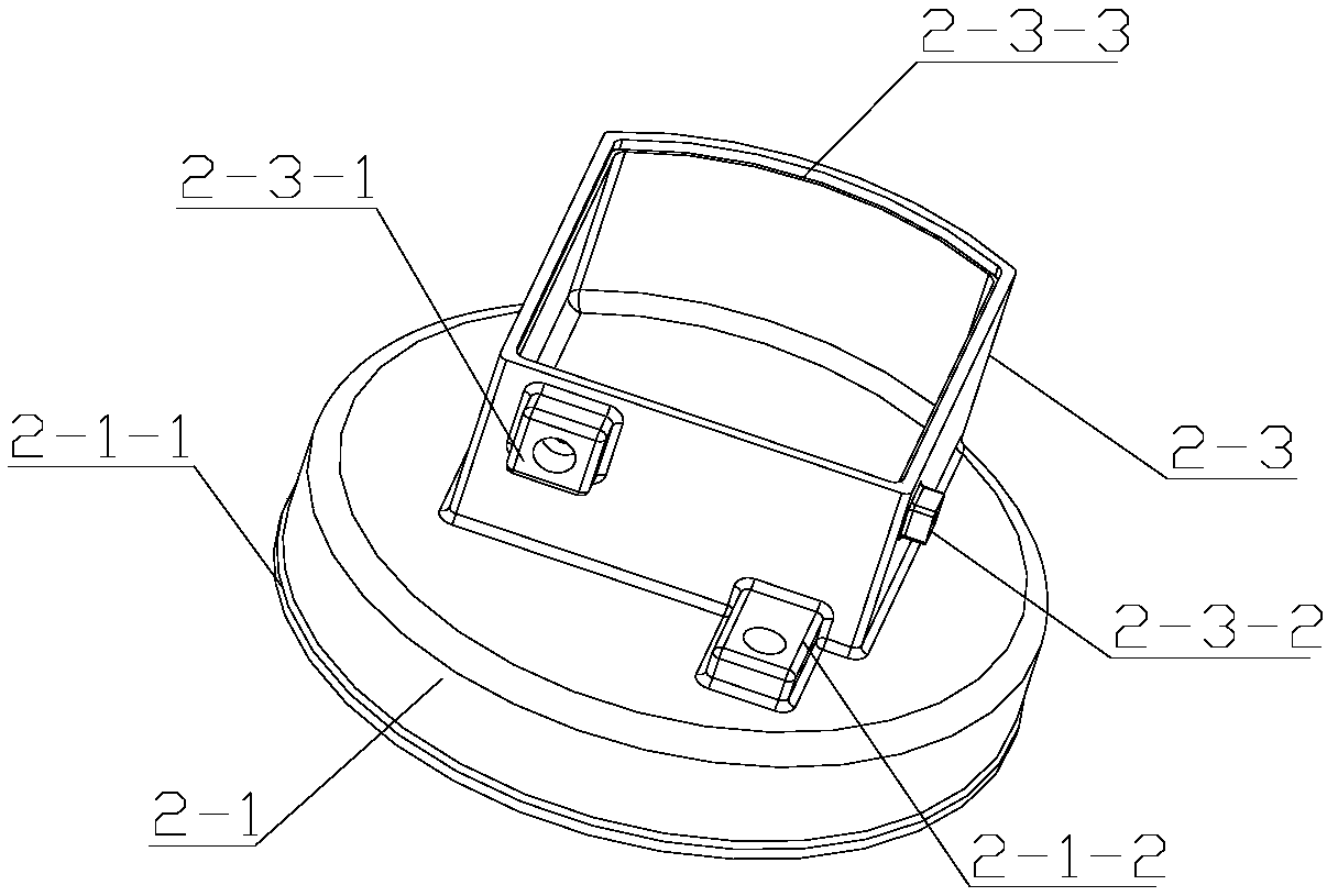
[0057] Such as figure 1 As shown, the ultra-high-strength stainless steel thick-wall pressure vessel is composed of a tank body 1, a top cover body 2, a cover plate 3, a conduit 4, and a nozzle 5.

[0058] 1) Parts processing ...

Embodiment 2

[0087] Embodiment 2 differs from Embodiment 1 in that:

[0088] The continuous welding process parameters of the tank girth seam are:

[0089] a. When the wall thickness of the tank is 5mm~6mm, the laser power is 4.2~4.8KW, the welding speed is 1.2~1.5m / min, the defocus amount is -1mm~2mm, and the shielding gas flow rate is 15~25L / min;

[0090] b. When the tank wall thickness is 6mm~7mm, the laser power is 4.7~5.4KW, the welding speed is 1.0~1.3m / min, the defocus amount is -1.5mm~2.5mm, and the protective gas flow rate is 15~25L / min;

[0091] c. When the wall thickness of the tank is 7mm~8mm, the laser power is 5.2~6.0KW, the welding speed is 0.8~1.2m / min, the defocus amount is -2mm~3mm, and the shielding gas flow rate is 15~25L / min;

[0092] d. When the tank wall thickness is 8mm~9mm, the laser power is 5.8~6.6KW, the welding speed is 0.8~1.2m / min, the defocus amount is -2mm~3mm, and the protective gas flow rate is 15~25L / min;

[0093] e. When the tank wall thickness is 9mm...


PUM

PropertyMeasurementUnit
thicknessaaaaaaaaaa
thicknessaaaaaaaaaa
thicknessaaaaaaaaaa

Abstract

The invention provides a laser welding method for a stainless steel thick-walled pressure vessel. The pressure vessel includes a high-pressure tank body, a low-pressure buffer pressure vessel and pipelines. The high-pressure tank body is made of solid-solution-strengthened or aging-strengthened stainless steel; The circular seam at the joint between the high-pressure tank and the low-pressure buffer pressure vessel is continuously welded by laser. The continuous welding parameters of the circular seam include: when the wall thickness of the tank is 5mm-10mm, the laser power is 4.2-7.5KW, the welding Speed ​​0.8~1.5m / min, defocus amount -2mm~3mm, protective gas flow 15~25L / min. The invention solves the welding strength problem of high-strength stainless steel materials in solid solution or age-strengthening state, has high and stable welding strength, and realizes equal-strength connection of base materials.

Description

technical field [0001] The invention belongs to the welding technical field of pressure vessels, in particular to a laser welding method for stainless steel thick-walled pressure vessels. Background technique [0002] At present, thick-walled pressure vessels are usually manufactured by arc welding multi-layer and multi-pass welding, and pressure vessels are often made of high-strength stainless steel materials such as solid solution strengthening and aging strengthening. Usually, after welding this material, in order to prevent weld The softening of the material in the heat-affected zone requires modulation treatment, but the device contains spring parts, sealing surfaces, etc., so heat treatment cannot be performed after welding. In order to meet the strength requirements, quenching and tempering treatment must be performed before welding and forming. The welding of high-strength materials in the modulated state requires strict control of welding parameters. However, when ...

Claims


Application Information

Patent Timeline
Patent Type & Authority Patents(China)
IPC IPC(8): B23K26/21B23K26/14B23K26/082B23K101/12
CPCB23K26/082B23K26/14B23K26/21B23K2101/12
Inventor 王维新万佩杜利刘巨锋付兴柏张书香丁永宏
Owner HUBEI SANJIANG AEROSPACE GRP HONGYANG ELECTROMECHANICAL
Why Eureka
Try Eureka