
Yarn tension adjusting mechanism of warp knitting machine

A technology for regulating mechanism and yarn tension, which is applied in warp knitting, textiles, papermaking, knitting, etc. It can solve the problem of uneven yarn tension and achieve uniform yarn tension and tension.

Pending Publication Date: 2022-01-28
SINCETECH FUJIAN TECH CO LTD
View PDF0 Cites 1 Cited by
  • Summary
  • Abstract
  • Description
  • Claims
  • Application Information

AI Technical Summary

Problems solved by technology

[0004] The purpose of the present invention is to overcome the above disadvantages and provide a warp knitting machine yarn tension adjustment mechanism to solve the problem of uneven yarn tension during existing yarn guides

Method used


Image

  • Yarn tension adjusting mechanism of warp knitting machine
  • Yarn tension adjusting mechanism of warp knitting machine
  • Yarn tension adjusting mechanism of warp knitting machine

Examples


Embodiment 1

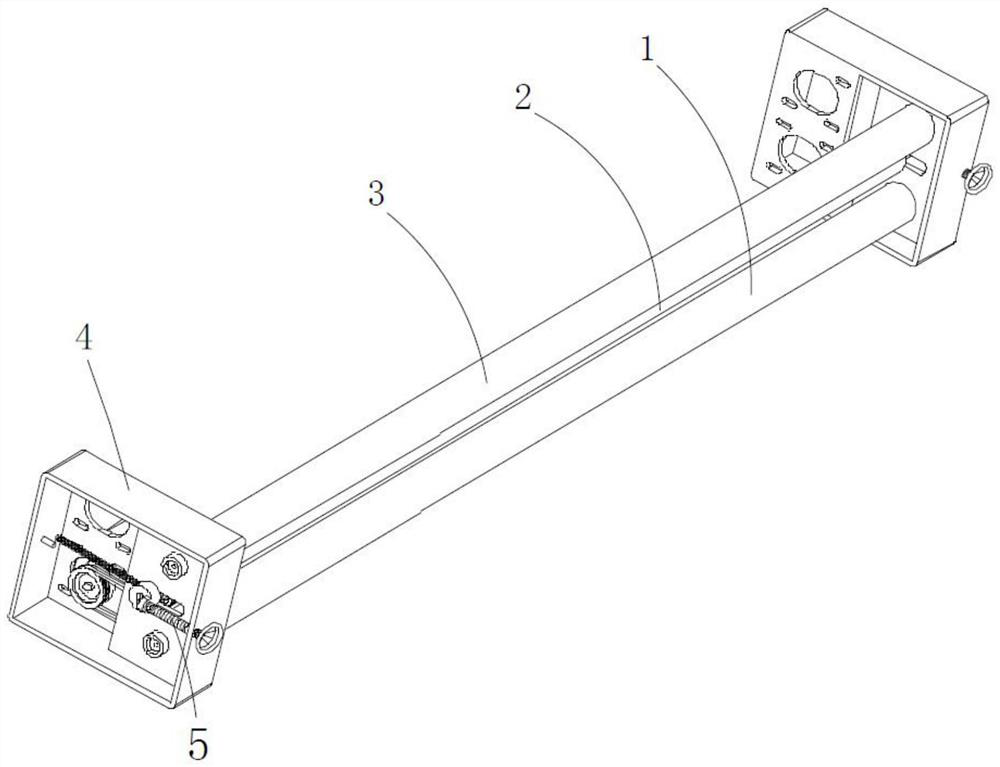
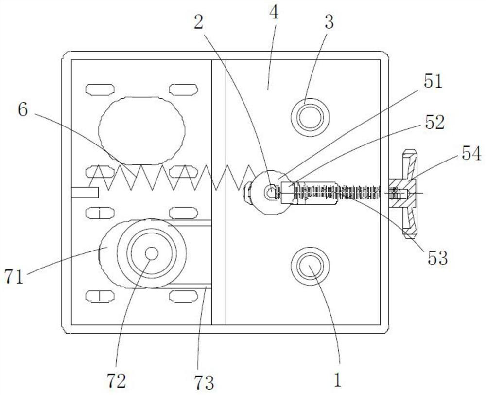
[0057] refer to Figure 1-3 , the present embodiment provides a warp knitting machine yarn tension adjustment mechanism, including a driving roller 1, a regulating roller 2 and a transition roller 3 arranged in sequence from top to bottom, and the regulating roller 2 moves left and right relative to the driving roller 1 and the transition roller 3 , the two ends of the driving roller 1, the regulating roller 2 and the transition roller 3 are all rotatably connected to the regulating mechanism 4; the driving roller 1, the regulating roller 2 and the transition roller 3 are arranged in a curve, and the driving roller 1 and the transition roller The axes between the 3 are on the same vertical line, wherein the yarn goes around the transition roller 3, the regulating roller 2 and the driving roller 1 in turn, so that the yarn is in the shape of a curve; the driving roller 1, the regulating roller 2 and the transition roller The surface of 3 is smooth, and the driving roller 1, reg...

Embodiment 2

[0067] refer to Figure 1-7 , this embodiment includes a transition roller 3 and a driving roller 1, the yarn reaches the transition roller 3 from the let-off mechanism, and the yarn is surrounded in an "S" shape from the side view between the transition roller 3 and the driving roller 1, thereby performing tension adjustment , the driving roller 1 mainly assists in pulling the yarn, and the original yarn itself has a certain pulling speed under the action of the pan head.

Embodiment 3

[0069] refer to Figure 1-7 , the difference between this embodiment and embodiment 2 is that the adjustment range of tension adjustment in embodiment 2 is relatively limited. In this embodiment, the driving roller 1 of embodiment 2 is replaced by the adjustment roller 2, and the adjustment roller 2 can be connected with the transition roller 3 presents an "S"-shaped wrapping angle with a large span for further tension control.


PUM


Abstract

The invention relates to the field of yarn tension adjustment, in particular to a yarn tension adjusting mechanism of a warp knitting machine, the yarn tension adjusting mechanism comprises a transition roller, an adjusting roller or a driving roller, and the adjusting mechanism comprises at least one of the transition roller, the adjusting roller or the driving roller or a combination of more than two rollers. Yarn is in a curve shape after bypassing the transition roller, the adjusting roller and the driving roller in sequence, the yarn can be pulled through rotation of the driving roller, the tension of the yarn is uniform, meanwhile, the distance between the adjusting roller and the transition roller relative to the driving roller is adjusted through the adjusting device, the contact area between the yarn and the driving roller as well as the contact area between the adjusting roller and the transition roller are adjusted, so that the tension for pulling the yarn can be correspondingly adjusted, the tension of the yarn can be more uniform, and the phenomenon of 'vertical lines' of cloth is avoided.

Description

technical field [0001] The invention relates to the technical field of tension adjustment mechanisms, in particular to a warp knitting machine yarn tension adjustment mechanism. Background technique [0002] With the progress of society, the textile industry has been greatly developed. In the weaving process, one or several groups of warp yarns arranged in parallel are then knitted by the warp knitting machine while pulling the yarn wound on the bobbin. The creel guides the yarn for further processing or for sale as a semi-finished product. When weaving yarn, after the yarn passes through the creel, it is easy to make the tension of multiple yarns uneven, and then make the yarn tightness, sometimes tight and sometimes loose will cause the cloth surface produced by the warp knitting machine to have broken yarn, Uneven mesh size, uneven single-needle stitch size, vertical stripes in color when multi-color yarn is knitted, uneven mesh size and stitch size will cause the phenom...

Claims


Application Information

Patent Timeline
Patent Type & Authority Applications(China)
IPC IPC(8): D04B27/14D04B27/02
CPCD04B27/14D04B27/02
Inventor 许金泰蔡金为刘恋张英东
Owner SINCETECH FUJIAN TECH CO LTD
Learn More