Novel hydraulic tail plate single-acting oil cylinder

A single-acting, hydraulic technology, which is applied in the direction of fluid pressure actuating devices, can solve the problems of shortened cylinder life, easy damage to seals, and difficulty in control, so as to change the contact degree, improve the wear resistance effect, and increase the service life. Effect

Pending Publication Date: 2022-01-28
LIUZHOU SHUANGJI MACHINERY
View PDF0 Cites 1 Cited by
  • Summary
  • Abstract
  • Description
  • Claims
  • Application Information

AI Technical Summary

Problems solved by technology

[0003] However, the conventional oil cylinder has the following disadvantages. The exhaust port of the conventional structure is on the cylinder barrel, and the cylinder must be welded with the exhaust port joint to protect the rod cavity. When this structure is welded, the inner hole of the cylinder barrel is easily deformed, resulting in difficulty in assembly. The exhaust hole must be drilled on the structural cylinder. Before assembly, the joint between the inner hole of the cylinder and the exhaust hole must be polished so as not to hurt the hand, so as to ensure that the seal will not be damaged during assembly. This process is extremely difficult to control, and it is easy to Damage the seal. The joint of the exhaust port of the conventional structure is usually equipped with a muffler or an air pipe, and the air pipe is connected to the fuel tank. Regardless of the assembly of the muffler or the air pipe, air will enter the rodless cavity, and the moisture in the air will make the cylinder in the rod cavity Rust, which reduces cylinder life

Method used


Image

  • Novel hydraulic tail plate single-acting oil cylinder
  • Novel hydraulic tail plate single-acting oil cylinder
  • Novel hydraulic tail plate single-acting oil cylinder

Examples


Embodiment Construction

[0026] The technical solutions in the embodiments of the present invention will be clearly and completely described below in conjunction with the accompanying drawings in the embodiments of the present invention. Obviously, the described embodiments are only some of the embodiments of the present invention, not all of them. Based on The embodiments of the present invention and all other embodiments obtained by persons of ordinary skill in the art without making creative efforts belong to the protection scope of the present invention.

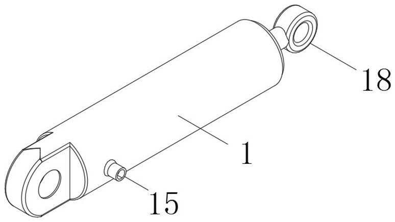
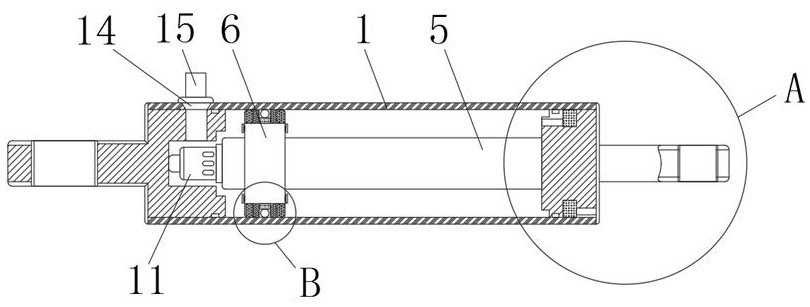
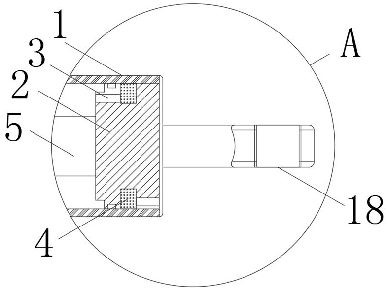
[0027] see Figure 1 to Figure 6 , the present invention provides a technical solution: a new hydraulic tailgate single-acting oil cylinder, including a cylinder body 1, a guide sleeve 2 is fixedly installed on one end of the cylinder body 1, an exhaust hole 3 is opened in the guide sleeve 2, and the guide sleeve 2 The middle part of the surface is provided with a felt layer 4, the vent hole 3 is set on the guide sleeve 2, and there is no vent h...


PUM


Abstract

The invention discloses a novel hydraulic tail plate single-action oil cylinder, which relates to the technical field of oil cylinders and comprises a cylinder body, a guide sleeve is fixedly mounted at one end of the cylinder body, an exhaust hole is formed in the guide sleeve, a felt layer is arranged in the middle of the surface of the guide sleeve, a rod part is arranged in the cylinder body, a piston part is sleeved on the surface of the rod part, and the piston part comprises a main piston. Anti-pollution oil seals are fixedly connected to the two sides of the surface of the main piston, and wear-resisting layers are arranged on the inner side walls of the anti-pollution oil seals. According to the novel hydraulic tail plate single-action oil cylinder, through the arrangement of the cylinder body, the guide sleeve, the exhaust hole and the felt layer, the exhaust hole is formed in the guide sleeve, no exhaust hole is formed in the cylinder barrel, and the problems that an inner hole of the cylinder barrel is prone to deformation during welding and a sealing element is damaged during assembly are solved. By adopting a felt layer, air in the rod cavity can be smoothly discharged, and moisture and the like in the air can be absorbed, so that the cylinder barrel in the rod cavity can be effectively prevented from rusting, and the service life of the device is prolonged.

Description

technical field [0001] The invention relates to the technical field of oil cylinders, in particular to a novel hydraulic tailgate single-acting oil cylinder. Background technique [0002] Tail lift is a kind of hydraulic lifting and unloading equipment installed at the rear of the vehicle and powered by the vehicle battery. The van truck equipped with a tail lift is not limited by the site, equipment and manpower when loading and unloading goods. Even if only one person can complete the cargo loading and unloading, the use of the tail lift is fast, safe and efficient, and can greatly improve the transportation. Efficiency is the necessary equipment for modern logistics and transportation. At present, it is widely used in logistics, finance, petrochemical, tobacco, commerce, manufacturing and other industries. Single-acting hydraulic cylinders refer to hydraulic cylinders that only input pressure oil from one side of the piston. The reset of the piston can only be done by m...

Claims


Application Information

Patent Timeline
Patent Type & Authority Applications(China)
IPC IPC(8): F15B15/14F15B15/20F15B15/22
CPCF15B15/1423F15B15/1428F15B15/1447F15B15/1471F15B15/1457F15B15/22F15B15/226
Inventor 李桂成何先敏阮涛谭覃洒盛余健
Owner LIUZHOU SHUANGJI MACHINERY
Why Eureka
Try Eureka