Bandgap reference voltage generating circuit

A technology for generating circuits and reference voltages, which can be used in adjusting electrical variables, control/regulating systems, instruments, etc., and can solve problems such as uncertainty in FET gate potential

Inactive Publication Date: 2004-02-25
PS4 LUXCO SARL
View PDF0 Cites 1 Cited by
  • Summary
  • Abstract
  • Description
  • Claims
  • Application Information

AI Technical Summary

Problems solved by technology

[0005] However, there is a problem in the bandgap reference voltage generating circuit of the above-mentioned prior art, that is, when the power supply is just turned on, the gate potential of each FET is uncertain, and as a result, a stable reference voltage Vo cannot be quickly obtained.

Method used


Image

  • Bandgap reference voltage generating circuit
  • Bandgap reference voltage generating circuit
  • Bandgap reference voltage generating circuit

Examples


Embodiment Construction

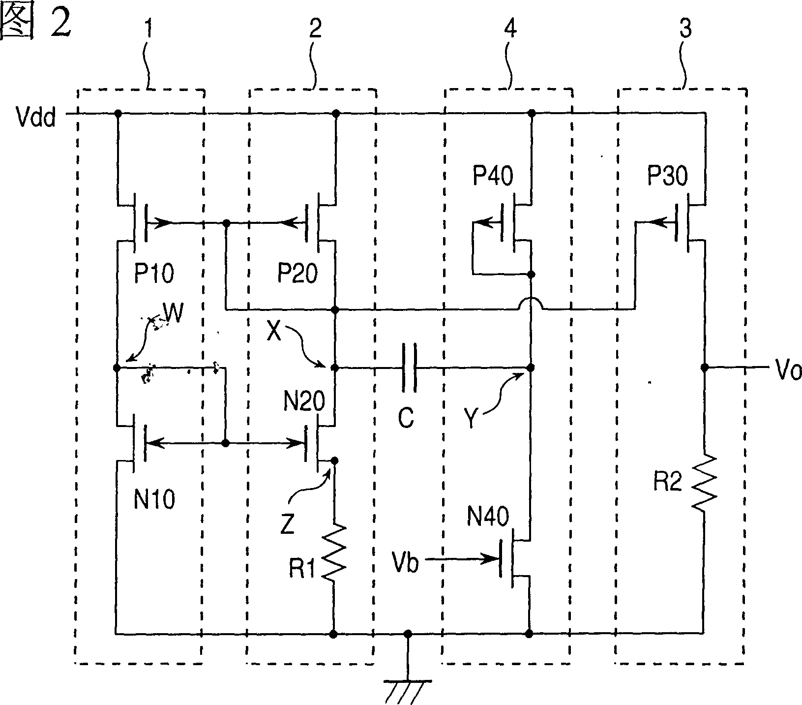
[0020] Referring to FIG. 2, there is shown a circuit diagram of a first embodiment of a bandgap reference voltage generating circuit according to the present invention.

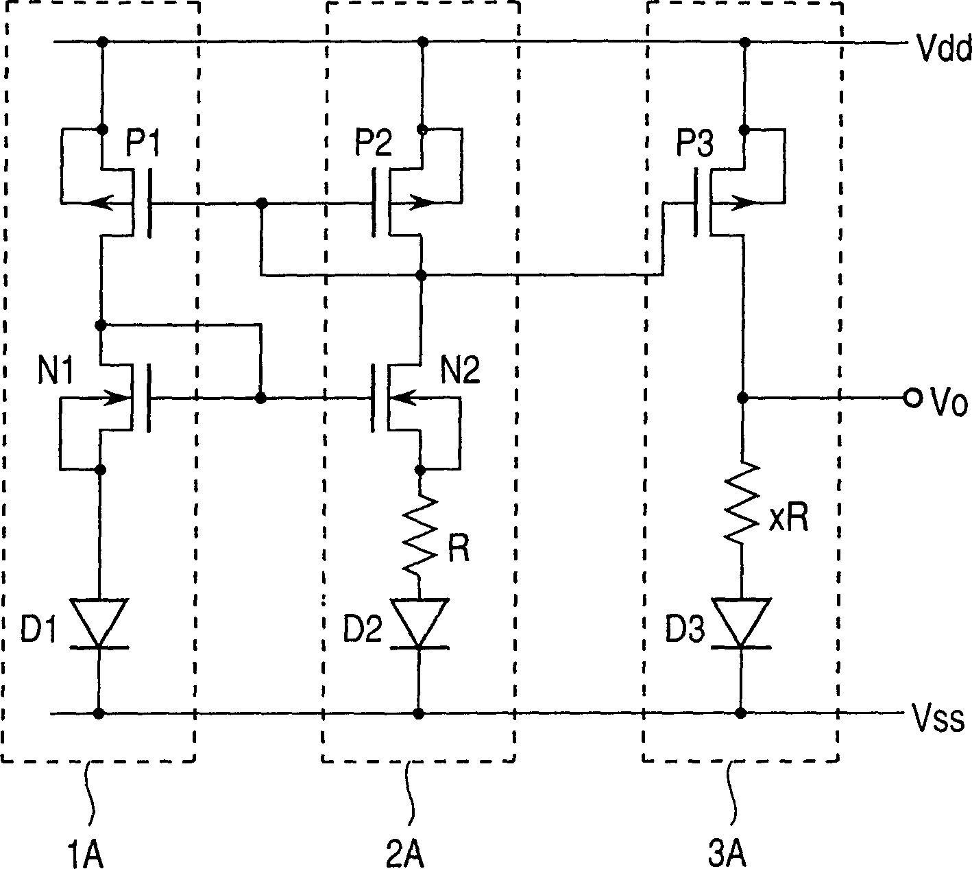
[0021] 1 and 2, it can be seen that the embodiment of the bandgap reference voltage generating circuit according to the present invention shown in FIG. To the bandgap reference voltage generating circuits of the unit circuits 1, 2 and 3 is added a fourth unit circuit 4 including an n-channel FET (N40) which is turned on in response to a bias voltage. Similar to the prior art bandgap reference voltage generating circuit, the first, second and third unit circuits 1, 2 and 3 are connected to each other.

[0022] Briefly, the first unit circuit 1 includes an n-channel FET N10 whose source is grounded and a p-channel FET P10 whose source is connected to the supply voltage Vdd and whose drain is connected to the gate and drain of the n-channel FET N10. The second unit circuit 2 includes a resistor R1 whose one end...


PUM


Abstract

In a bandgap reference voltage generating circuit having first, second and third unitary circuits connected in parallel between a power supply voltage and a ground, there is added a fourth unitary circuit including an n-channel FET turned on in response to a bias voltage applied to a gate of the n-channel FET. The second unitary circuit is connected to the fourth unitary circuit through a capacitor having one end connected to a drain of the n-channel FET. When the bias voltage is applied to turn on the n-channel FET of the fourth unitary circuit, since the potential of the one end of the capacitor is dropped, a gate potential of n-channel FETs included in the first and second unitary circuits and operating in a weak inversion condition quickly becomes definite, so that a reference voltage can be generated quickly.

Description

technical field [0001] The present invention generally relates to a bandgap reference voltage generating circuit, and particularly relates to a bandgap reference voltage generating circuit with improved response speed. Background technique [0002] In the prior art, since a stable reference voltage is required to drive integrated circuits or other electronic devices, a bandgap reference voltage generating circuit is often used. Referring to FIG. 1, an example of a prior art bandgap reference voltage generating circuit is shown. [0003] The prior art bandgap reference voltage generating circuit as shown in FIG. 1 includes first, second and third unit circuits 1A, 2A and 3A to which a power supply voltage Vdd is loaded to cause the first and second unit circuits to pass through The n-channel field effect transistors (FETs) N1 and N2 of 1A and 2A operate in a weak inversion state to generate a reference voltage Vo determined by the energy band structure of the semiconductor. ...

Claims


Application Information

Patent Timeline
IPC IPC(8): G05F3/02G05F3/24G05F3/26
CPCG05F3/242G05F3/262G05F3/02
Inventor 小野寺忠
Owner PS4 LUXCO SARL
Why Eureka
Try Eureka