Noise suppression method suitable for high speed sampling system

A noise suppression and high-speed sampling technology, applied in the field of noise suppression, can solve the problems of low signal frequency, few application fields, and few researches, and achieve the effects of preventing electromagnetic interference, reducing common-mode interference, and shortening the length of traces

Inactive Publication Date: 2019-02-19
CHENGDU GOLDTEL IND GROUP
View PDF8 Cites 0 Cited by
  • Summary
  • Abstract
  • Description
  • Claims
  • Application Information

AI Technical Summary

Problems solved by technology

[0004] As the core component of communication, radar and imaging systems, high-speed acquisition system has always been a hot spot and focus of research at home and abroad. Previous acquisition systems for communication and radar applications have a sampling accuracy of 14 to 16 bits and a sampling rate of 80 to 200 MSPS; For color Doppler ultrasound and other medical imaging systems, the ADC sampling accuracy is basically 12bit, and the sampling rate is >10MSPS; oscilloscopes and other measurement equipment require extremely high sampling rates (oscilloscopes with a bandwidth of 500M usually have a sampling rate exceeding 2.5GSPS), but the sampling accuracy is not high, usually Only need 8bit
[0005] High-precision acquisition system 18~24bit, usually in industrial measurement and other fields, such as scales, flowmeters, because a large dynamic range is required, usually requires 24bit resolution accuracy, but because the collected signal frequency is very low, usually below kHz, So the sampling speed of the ADC is not high (usually a few ksps to tens of ksps)
[0006] To sum up, it can be seen that for the acquisition system with a sampling accuracy of 18bit and a high sampling rate (5MSPS), there are not many researches due to fewer application fields.

Method used


Image

  • Noise suppression method suitable for high speed sampling system
  • Noise suppression method suitable for high speed sampling system
  • Noise suppression method suitable for high speed sampling system

Examples


Embodiment Construction

[0028] The technical solutions of the present invention will be clearly and completely described below in conjunction with the embodiments. Apparently, the described embodiments are only some of the embodiments of the present invention, not all of them. Based on the embodiments of the present invention, all other embodiments obtained by those skilled in the art without making creative efforts belong to the protection scope of the present invention.

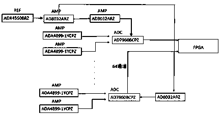
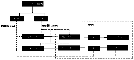
[0029] refer to Figure 1-4 , the present invention provides a technical solution: a noise suppression method suitable for a high-speed sampling system, the sampling system includes a clock generation module, a frequency division unit, a frequency multiplication unit, an ADC module, an FPGA module, and a power supply, and the clock generation The clock signal output terminals of the module are respectively connected to the frequency division unit and the frequency multiplication unit. The clock generation module generates the cloc...


PUM


Abstract

The invention discloses a noise suppression method suitable for a high speed sampling system. The sampling system comprises a clock generation module, a frequency dividing unit, a frequency doubling unit, an ADC (Analog-to-Digital Converter) module, an FPGA (Field-Programmable Gate Array) module, and a power supply. The noise suppression method comprises the following steps: S1, adopting an LDO--ADM7151 low dropout voltage regulator as an analog part power supply, adopting an ADR4550BRZ voltage chip as a digital part power supply, and connecting an output end of the ADR4550BRZ voltage chip with a 20uF tantalum capacitor to ensure stability of a reference voltage of the ADC when sampling; S2, dividing the sampling system into a digital ground and an analog ground, and connecting the digitalground and the analog ground together at a power supply to ensure noises of the digital part not conduct to the simulation part; and S3, reducing common mode interference by adopting a full-differential input mode, and adding a shielding cover in the analog part to prevent electromagnetic interference. According to the noise suppression method suitable for the high speed sampling system, noise equivalent of the whole system is smaller than 0.076mV at an input end of the ADC, and an design index of the system ENOB=16 bit is satisfied.

Description

technical field [0001] The invention relates to the technical field of noise suppression, in particular to a noise suppression method suitable for high-speed sampling systems. Background technique [0002] With the rapid development of terahertz technology, terahertz imaging has been used more and more widely. Compared with X-ray imaging, terahertz imaging has the advantages of low transmission power and no harm to the human body. At the same time, terahertz imaging also has the characteristics of high bandwidth. , maintaining the advantages of high resolution and fine imaging of X imaging, so it is more and more widely used in airports, high-speed rail and other security inspection fields and public security systems. [0003] Terahertz imaging puts forward higher requirements for the acquisition system: because of the large bandwidth, the acquisition system is required to have a higher sampling rate; and because of the large dynamic range and high contrast required by imagi...

Claims


Application Information

Patent Timeline
Patent Type & Authority Applications(China)
IPC IPC(8): G05B19/042
CPCG05B19/0425G05B2219/2612
Inventor 彭光辉陶磊赵启卫黄丽洪
Owner CHENGDU GOLDTEL IND GROUP
Why Eureka
Try Eureka