Cabinet door interlocking device for switch equipment and switch equipment

A technology of interlocking device and switchgear, which is applied in the direction of electric switches, electrical components, circuits, etc., can solve the problems of not allowing circuit breakers, complicated operation process, high cost, etc., and achieve reliable reverse locking, high strength, and reliable locking function Effect

Pending Publication Date: 2022-01-28
XUCHANG XJ SOFTWARE TECH +1
View PDF13 Cites 0 Cited by
  • Summary
  • Abstract
  • Description
  • Claims
  • Application Information

AI Technical Summary

Problems solved by technology

[0004] At present, most of the measures taken by the five defenses are to install live indicators and electromagnetic locks on the door of the cable room. In this way, when the switchgear is charged, the indicator light of the live indicator lights up to remind that there is electricity. At the same time, the electromagnetic lock of the cable room door is locked. door won't open
However, the disadvantage of this design is that the cost of required components is high, and holes for installing live indicators and electromagnetic locks must be opened on the cable compartment door, especially when the cable compartment door is in the open state, because the electromagnetic lock does not work , it is also necessary to take measures that do not allow the circuit breaker to open
The whole operation process is complicated and the cost is also high
In addition, most of the existing purely mechanical interlocks only have forward interlocking (that is, the cable room door cannot be opened in the non-maintenance grounding state), but no reverse locking (that is, the circuit breaker and the grounding switch are not allowed to open after the cable room door is opened. )
Some have positive and negative mechanical interlocks, the reverse locking can be unlocked manually, and the layout of the interlocking devices is scattered and chaotic

Method used


Image

  • Cabinet door interlocking device for switch equipment and switch equipment
  • Cabinet door interlocking device for switch equipment and switch equipment
  • Cabinet door interlocking device for switch equipment and switch equipment

Examples


Embodiment Construction

[0030] In order to make the object, technical solution and advantages of the present invention clearer, the present invention will be further described in detail below in combination with specific embodiments and with reference to the accompanying drawings. It should be understood that these descriptions are exemplary only, and are not intended to limit the scope of the present invention. Also, in the following description, descriptions of well-known structures and techniques are omitted to avoid unnecessarily obscuring the concept of the present invention.

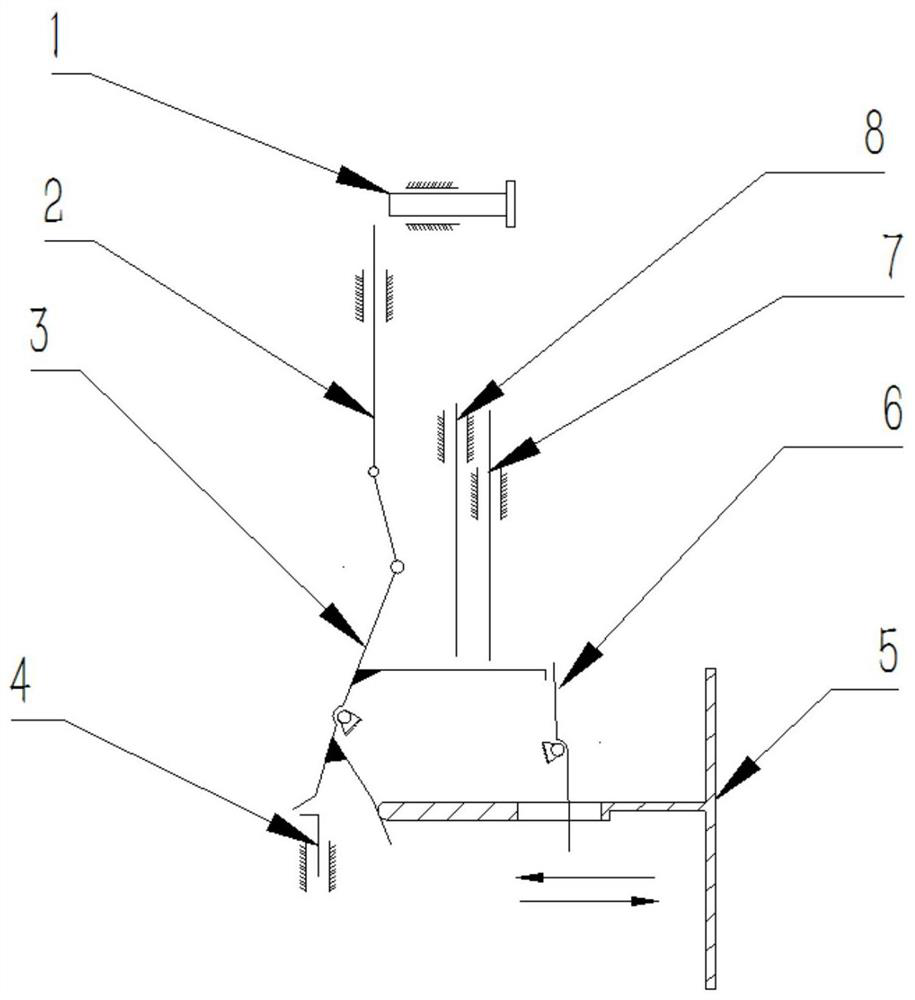
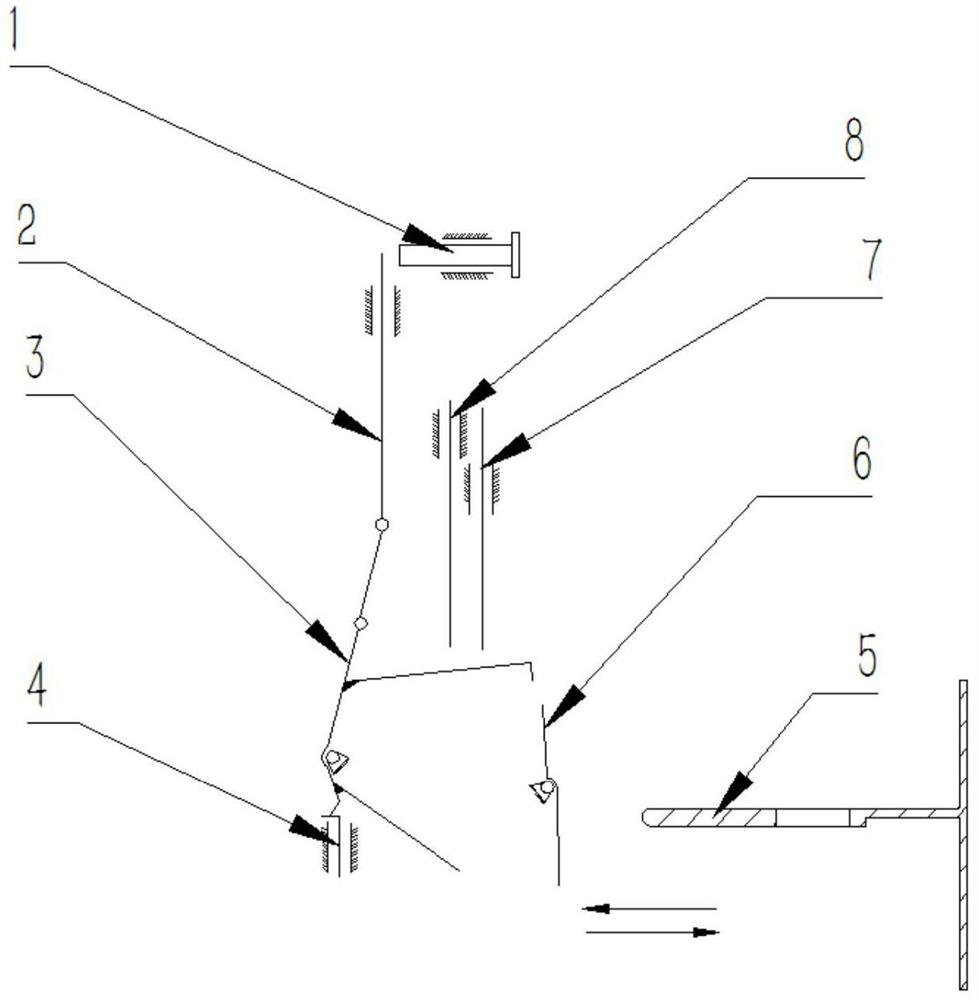
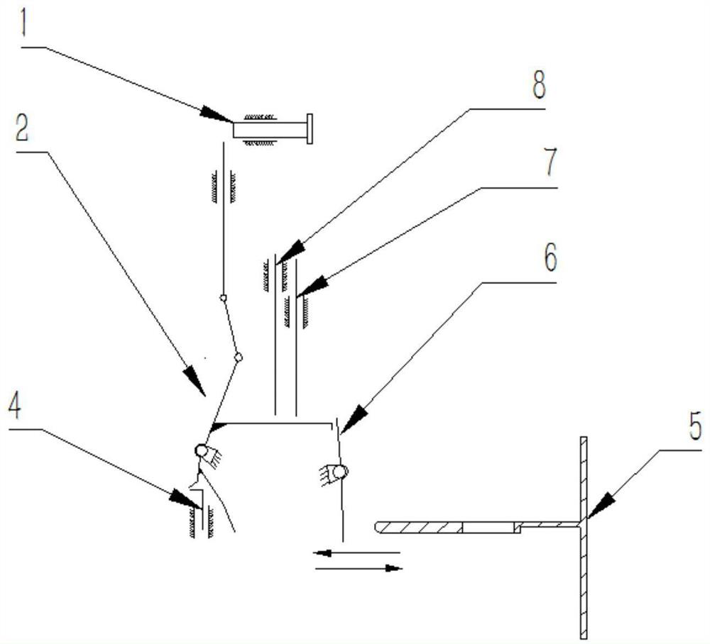
[0031] The first aspect of the present invention provides a cabinet door interlocking device for switchgear, including an interlocking device box and an interlocking mechanism fixed in the interlocking device box. Such as Figure 1-3 As shown, the interlock mechanism includes opening limit plate 2, interlock plate 3, position switch 4, interlock limit block 6, grounding / isolating switch interlock lever 7 and circuit brea...


PUM


Abstract

The invention discloses a cabinet door interlocking device for switch equipment and the switch equipment. The interlocking device comprises an interlocking device box and an interlocking mechanism fixed in the interlocking device box; the interlocking mechanism comprises an opening limiting plate, an interlocking plate, a position switch, an interlocking limiting block, a grounding / isolating switch interlocking rod and a circuit breaker mechanism interlocking rod; the opening limiting plate, the interlocking plate and the position switch are arranged in sequence; the interlocking limiting block is arranged near the interlocking plate, and the interlocking plate limits the interlocking limiting block; the interlocking plate is adjacent to the grounding / disconnecting switch interlocking rod and the circuit breaker mechanism interlocking rod, and the grounding / disconnecting switch interlocking rod and the circuit breaker mechanism interlocking rod limit the interlocking plate; the rotation of the interlocking limiting block limits the cabinet door or relieves the limit of the cabinet door, so that the cabinet door is in an openable state or a non-openable state. According to the interlocking device, forward and reverse locking integrated modular design can be achieved, and the effects that a forward locking device is high in strength and reverse locking is reliable are achieved.

Description

technical field [0001] The invention relates to the field of electrical switchgear, in particular to a cabinet door interlocking device system and switchgear for switchgear. Background technique [0002] Five preventions usually refers to the abbreviation of five anti-mistake functions for high-voltage electrical equipment to ensure personal safety, and is one of the important measures for electric safety. The specific connotations of the five preventions are: 1. Prevent opening and closing of the isolating switch with load; 2. Prevent wrong opening and closing of the circuit breaker; into the electrified interval. [0003] In switchgear, the main circuit consists of a disconnector or earthing switch or a circuit breaker. In the main circuit system, the cable room door, circuit breaker, disconnector or grounding switch must be interlocked to reflect the above five defenses. [0004] At present, most of the measures taken by the five defenses are to install live indicators...

Claims


Application Information

Patent Timeline
Patent Type & Authority Applications(China)
IPC IPC(8): H01H9/22
CPCH01H9/22
Inventor 白维正李龙江廖红兵董冏郑晓果王其中吴小钊李猛遵明伟于盟宋晓生梁利娟
Owner XUCHANG XJ SOFTWARE TECH
Why Eureka
Try Eureka