
A receiver and its automatic gain control method

An automatic gain control and receiver technology, applied in the field of communications, can solve the problems of limited quantization accuracy of peak detection circuits, affecting the receiver AGC dynamic range, and high cost of weak RF signals, achieving high-precision automatic gain control and speeding up closed-loop response speed , the effect of high gain control accuracy

Active Publication Date: 2022-06-24
SOUTH CHINA UNIV OF TECH +1
View PDF7 Cites 0 Cited by
  • Summary
  • Abstract
  • Description
  • Claims
  • Application Information

AI Technical Summary

Problems solved by technology

The feedback type AGC loop of the existing receiver such as figure 1 As shown, the advantage of digital feedback AGC is higher precision, but the disadvantage is slower convergence speed
Another common AGC loop is a feed-forward structure, such as figure 2 As shown, the feed-forward AGC converges faster than the feedback AGC, but due to the limited quantization accuracy of the peak detection circuit, it is difficult to achieve accurate AGC control; and the detection of weak radio frequency signals is expensive, and is often only used to control low-frequency analog signals , thus affecting the dynamic range of the receiver AGC

Method used


Image

  • A receiver and its automatic gain control method
  • A receiver and its automatic gain control method
  • A receiver and its automatic gain control method

Examples


Embodiment Construction

[0046] The present invention will be further described below with reference to the specific embodiments in the accompanying drawings.

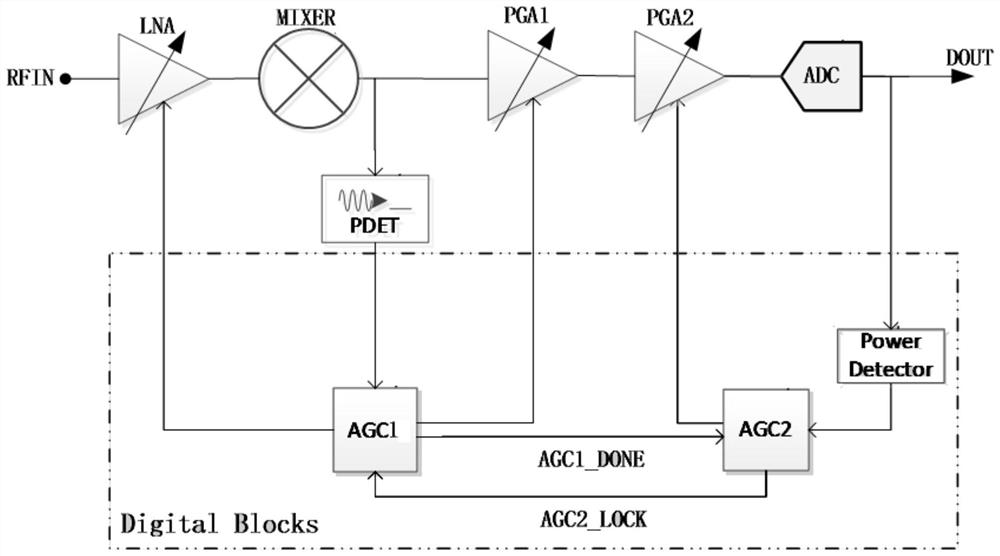
[0047] see image 3 , 4 , a receiver comprising a low noise amplifier LNA, a downconverter MIXER, a first programmable gain amplifier PGA1, a second programmable gain amplifier PGA2, an analog-to-digital converter ADC, an analog signal peak detection circuit PDET, and a digital power detection unit Power Detector, the first automatic gain control algorithm unit AGC1 and the second automatic gain control algorithm unit AGC2; the low noise amplifier LNA is connected to the downconverter MIXER, the first programmable gain amplifier PGA1, the second programmable gain amplifier PGA2, the analog-digital The converter ADC, the first automatic gain control algorithm unit AGC1 are respectively connected to the control end of the low noise amplifier LNA and the control end of the first programmable gain amplifier PGA1, and the output end of the downconve...


PUM


Abstract

The invention discloses a receiver, which relates to the technical field of communication and solves the technical problems of the existing receiver automatic gain control with small dynamic range, slow convergence speed and poor precision. The low-noise amplifier in the receiver is sequentially connected to the down-converter , the first programmable gain amplifier, the second programmable gain amplifier, the analog-to-digital converter, and the first automatic gain control algorithm unit are respectively connected to the control end of the low noise amplifier, the control end of the first programmable gain amplifier, and the down converter The output terminal is connected to the first automatic gain control algorithm unit through the analog signal peak detection circuit, and the output terminal of the analog-to-digital converter is connected to the control terminal of the second programmable gain amplifier through the digital power detection unit and the second automatic gain control algorithm unit successively. An automatic gain control algorithm unit is connected to the second automatic gain control algorithm unit. The invention also discloses a receiver automatic gain control method.

Description

technical field [0001] The present invention relates to the technical field of communications, and more particularly, to a receiver and an automatic gain control method thereof. Background technique [0002] The signal processed by the receiver comes from outside the receiver. The strength of the signal power depends on the size of the signal source and the attenuation of the propagation path. The interference outside the signal often falls into the receiving frequency band for some reasons. Therefore, the size of the signal processed by the receiver at different times may be very different. In order to achieve better performance, the gain of the receiver needs to be able to be automatically controlled according to the size of the processed signal, that is, the automatic gain control (Auto Gain Control) system . [0003] The automatic gain control loop is generally placed between the analog and digital circuits, the gain control algorithm is implemented in the digital part,...

Claims


Application Information

Patent Timeline
Patent Type & Authority Patents(China)
IPC IPC(8): H03G3/30H04B1/10H04B1/16
CPCH03G3/3036H04B1/10H04B1/16
Inventor 王日炎李斌钟世广吴朝晖周伶俐陈志坚
Owner SOUTH CHINA UNIV OF TECH
Learn More