
Dimming and toning circuit

A circuit and dimming technology, applied in electrical components and other directions, can solve problems such as complex circuits and inconvenient maintenance, and achieve the effect of simple circuit structure, high applicability, and improved experience.

Pending Publication Date: 2022-01-28
NINGBO SDIAPER OPTOELECTRONICS
View PDF0 Cites 0 Cited by
  • Summary
  • Abstract
  • Description
  • Claims
  • Application Information

AI Technical Summary

Problems solved by technology

On the one hand, there is the defect that the circuit for controlling the lighting device for dimming and color adjustment is relatively complicated; on the other hand, when the lighting device fails, it is necessary to check the program in the single-chip microcomputer system and check the hardware facilities. The hardware facilities of the single-chip microcomputer system are integrated circuits, which are not easy to maintain

Method used


Image

  • Dimming and toning circuit
  • Dimming and toning circuit
  • Dimming and toning circuit

Examples


Embodiment Construction

[0037] The present invention will be described in detail below in conjunction with the accompanying drawings and specific embodiments. The present invention is not limited to this embodiment, and other embodiments may also belong to the scope of the present invention as long as they conform to the gist of the present invention.

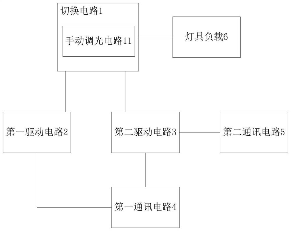
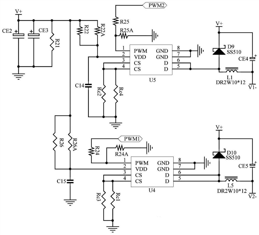
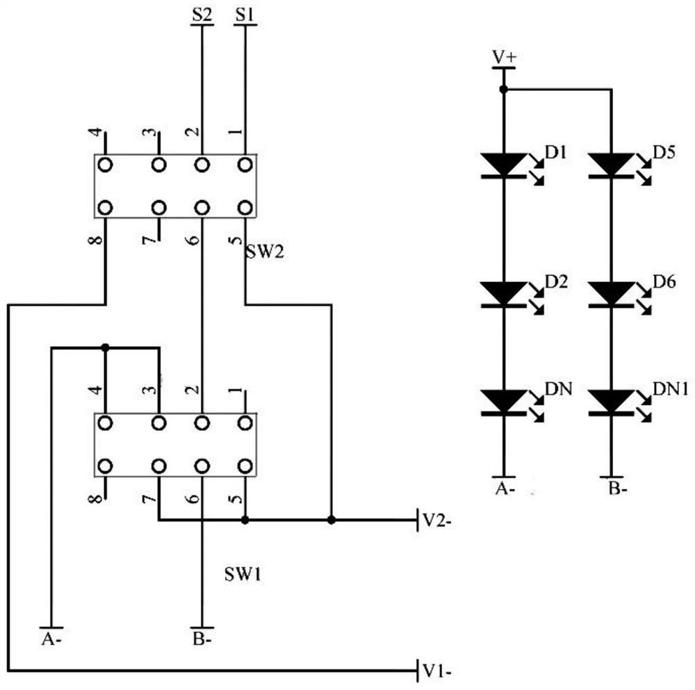
[0038] In a preferred embodiment of the present invention, based on the above-mentioned problems in the prior art, a dimming and temperature regulating circuit is now provided, such as Figure 1 to Figure 5 shown, including:

[0039] The switching circuit 1 is used to switch between an intelligent mode, a microwave mode and a manual mode according to a user's switching instruction;

[0040] The first driving circuit 2 is connected to the first output end of the switching circuit 1, and is used to obtain a first adjustment signal input from the outside, and adjust the current value of the output end of the first driving circuit 2 according to the firs...


PUM


Abstract

The present invention provides a dimming and toning circuit. The circuit comprises: a switching circuit used for performing switching among an intelligent mode, a microwave mode and a manual mode according to a switching instruction; a first driving circuit which acquires a first adjusting signal to adjust the current value of the output end of the first driving circuit; and a second driving circuit which acquires a second adjusting signal to adjust the current value of the output end of the second driving circuit. In the intelligent mode, a cold white light load performs power adjustment according to the current value output by the first driving circuit, and a warm white light load performs power regulation according to the current value output by the second driving circuit; in the microwave mode, the cold white light load and the warm white light load perform power adjustment according to the current value output by the second driving circuit; and in the manual mode, the power of the cold white light load and the power of the warm white light load are adjusted according to a dimming instruction. The dimming and toning circuit has the beneficial effects that: the circuit structure is simple, the cost is low, a user can select the operation mode of dimming and color modulation, and the use experience is improved.

Description

technical field [0001] The invention relates to the technical field of light-emitting diode regulation, in particular to a light-adjusting and color-adjusting circuit. Background technique [0002] At present, lighting devices based on light-emitting diodes are widely used in daily life, among which lighting devices that support lighting brightness adjustment and lighting color temperature adjustment are particularly popular. [0003] The adjustment of lighting brightness is dimming, which is realized by adjusting the power of the lamp load in the lighting device; the adjustment of lighting color temperature is temperature adjustment. The lamp load includes cool white load and warm white load. By adjusting the power of cool white load and warm white load respectively, To achieve color temperature adjustment, for example: when the power of the cool white load is high and the power of the warm white load is low, the color temperature of the lighting load of the lamp is low at ...

Claims


Application Information

Patent Timeline
IPC IPC(8): H05B45/10H05B45/20H05B45/34H05B45/40H05B45/50H05B45/30
CPCH05B45/10H05B45/20H05B45/34H05B45/40H05B45/50H05B45/30Y02B20/40
Inventor 昝金林曲志华张川龙
Owner NINGBO SDIAPER OPTOELECTRONICS
Learn More