
Scroll compressor

A scroll compressor and scroll tooth technology, applied in the field of scroll compressors, can solve the problems of unable to suppress refrigerant leakage and increase the gap area, so as to reduce refrigerant leakage, ensure reliability and reduce the gap Effect

Active Publication Date: 2022-01-28
MITSUBISHI ELECTRIC CORP
View PDF9 Cites 2 Cited by
  • Summary
  • Abstract
  • Description
  • Claims
  • Application Information

AI Technical Summary

Problems solved by technology

Therefore, the gap area between the crest of the scroll teeth and the base on the platen side becomes large, and the occurrence of refrigerant leakage cannot be suppressed, and there is a problem that the compression efficiency cannot be avoided.

Method used


Image

  • Scroll compressor
  • Scroll compressor
  • Scroll compressor

Examples


Embodiment approach 1

[0021]

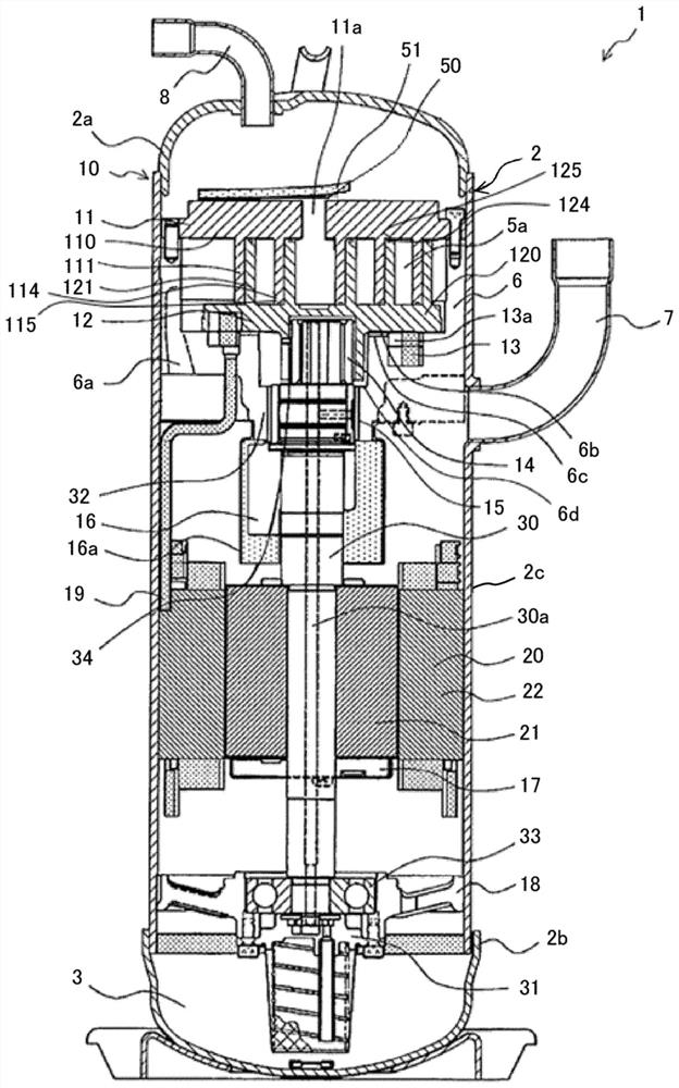
[0022] refer to figure 1 The scroll compressor 1 according to Embodiment 1 of the present invention will be described. figure 1 It is a longitudinal cross-sectional view schematically showing the scroll compressor 1 according to the first embodiment. Such as figure 1 As shown, the scroll compressor 1 includes a compression mechanism unit 10 and a motor 20 as a motor unit that drives the compression mechanism unit 10 inside a casing 2 that is a hermetic container.

[0023] The casing 2 has an upper casing 2 a , a lower casing 2 b , and a main body casing 2 c to constitute a casing of the scroll compressor 1 , and has an oil reservoir 3 at a lower portion. The housing 2 is cylindrical with a bottom, and the upper part of the main body housing 2c is closed by the dome-shaped upper housing 2a, and the lower part of the main body housing 2c is closed by the lower housing 2b.

[0024] The compression mechanism unit 10 is configured to include a fixed scroll 11 and an o...

Embodiment approach 2

[0070] Next, refer to Figure 6 Embodiment 2 of the present invention will be described. Figure 6 It is a plan view showing the orbiting scroll 12 of the scroll compressor 1 according to the second embodiment. In addition, here, the same code|symbol is attached|subjected to the same component as Embodiment 1 mentioned above, and the detailed description is abbreviate|omitted.

[0071] Such as Figure 6 As shown, in the second embodiment, the second swing-side base curved portion 128b of the swing scroll 12 is formed at a center-side end point 130a of the outer involute curve 130 in the wrap tooth 121 as a starting point and on the inner side. The outer peripheral end point 131b of the involute curve 131 is the range of the first arc portion 132 and the second arc portion 133 that end. That is, in the second embodiment, the second swing-side base curved portion 128 b of the swing scroll 12 is formed to extend into the wrap 121 beyond the range including the first arc portio...


PUM


Abstract

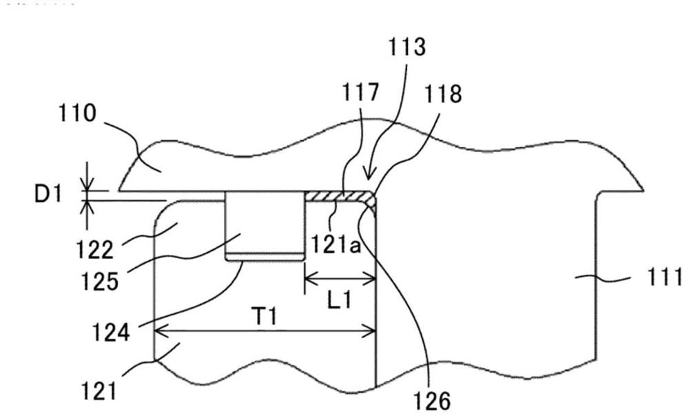
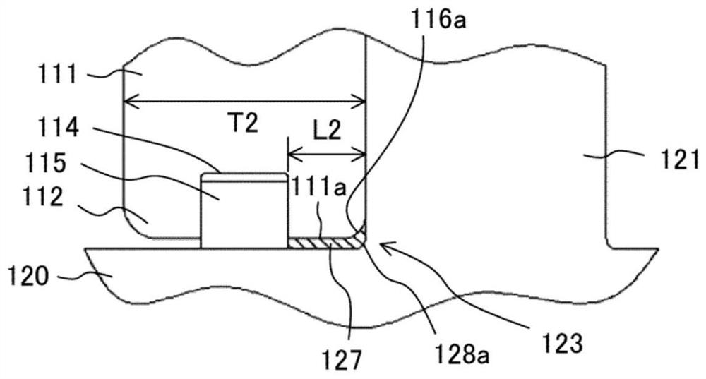
The present invention comprises: a fixed scroll in which a first fixed-side tooth tip curved section and a second fixed-side tooth tip curved section having a larger curvature radius than the foregoing first section are formed on a tooth tip of a scroll tooth, and in which a fixed-side root curved section is formed in a root section on a fixed table plate side of the scroll tooth; and a rocking scroll in which a rocking-side tooth tip curved section is formed on a tooth tip of the scroll tooth, and in which a first rocking-side root curved section and a second rocking-side root curved section having a larger curvature radius than that the foregoing first section are formed in a root section on a rocking table plate side of the scroll tooth. The second fixed-side tooth tip curved section and the second rocking-side root curved section are formed, in a scroll tooth of each scroll, in at least a part of or an entirety of a range including: a first arc section extending from a center-side end point of an outer involute curve toward a scroll center; and a second arc section extending from a center-side end point of an inner involute curve toward the scroll center. Due to this configuration, refrigerant leakage can be reduced while sufficiently ensuring fatigue strength at the center of the scroll tooth, and the compression efficiency can be improved while ensuring reliability.

Description

technical field [0001] The present invention relates to a scroll compressor including a fixed scroll and an orbiting scroll. Background technique [0002] A scroll compressor is provided with a fixed scroll and an orbiting scroll, wherein the fixed scroll has an involute-shaped wrap projectingly formed on a fixed platen, and the orbiting scroll has an orbiting scroll projectingly formed on an orbiting scroll. The involute-shaped wrap teeth on the table plate, the scroll compressor engages the wrap teeth of the fixed scroll and the swing scroll. At this time, the fixed scroll and the oscillating scroll are in contact with each other on their wrap sides with the phases of their wraps shifted by 180° relative to each other. Furthermore, by causing the orbiting scroll to orbit with respect to the fixed scroll, the plurality of compression chambers constituted by the fixed scroll and the orbiting scroll are gradually reduced from the outside to the inside, thereby compressing th...

Claims


Application Information

Patent Timeline
Patent Type & Authority Applications(China)
IPC IPC(8): F04C18/02
CPCF04C18/02
Inventor 鹈饲光融矢野贤司松井友寿高村祐司福原功一
Owner MITSUBISHI ELECTRIC CORP
Learn More