Ceramic pot glazing device for porcelain production
A ceramic pot and porcelain technology, which is applied in ceramic molding machines, auxiliary molding equipment, manufacturing tools, etc., can solve problems such as poor stability, and achieve the effect of increasing speed and improving efficiency
- Summary
- Abstract
- Description
- Claims
- Application Information
AI Technical Summary
Problems solved by technology
Method used
Image
Examples
Embodiment 1
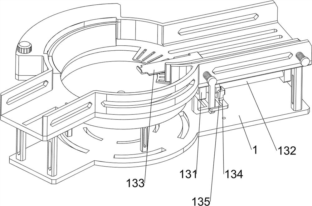
[0087] A ceramic pan glazing device for porcelain production, such as figure 1 and figure 2 As shown, include a first support frame 1, a first movable plate 2, a first compression spring 3, a water storage tank 4, a cover 5, a second movable plate 6, a second compression spring 7, a sponge 8, a limit mechanism 9 and Suction mechanism 10, the upper right part of the first support frame 1 is slidingly provided with the first movable plate 2, and the left and right sides of the first movable plate 2 are connected with the first compression spring 3 between the first support frame 1, The first compression spring 3 is wound on the first movable plate 2, the first support frame 1 is provided with a water storage tank 4 on the rear side of the middle part, the left side of the water storage tank 4 is threadedly connected with a cover 5, and the front side of the water storage tank 4 is slidable. There is a second movable plate 6, and the second movable plate 6 is connected with the...
Embodiment 2
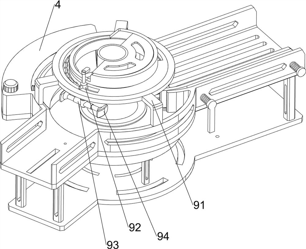
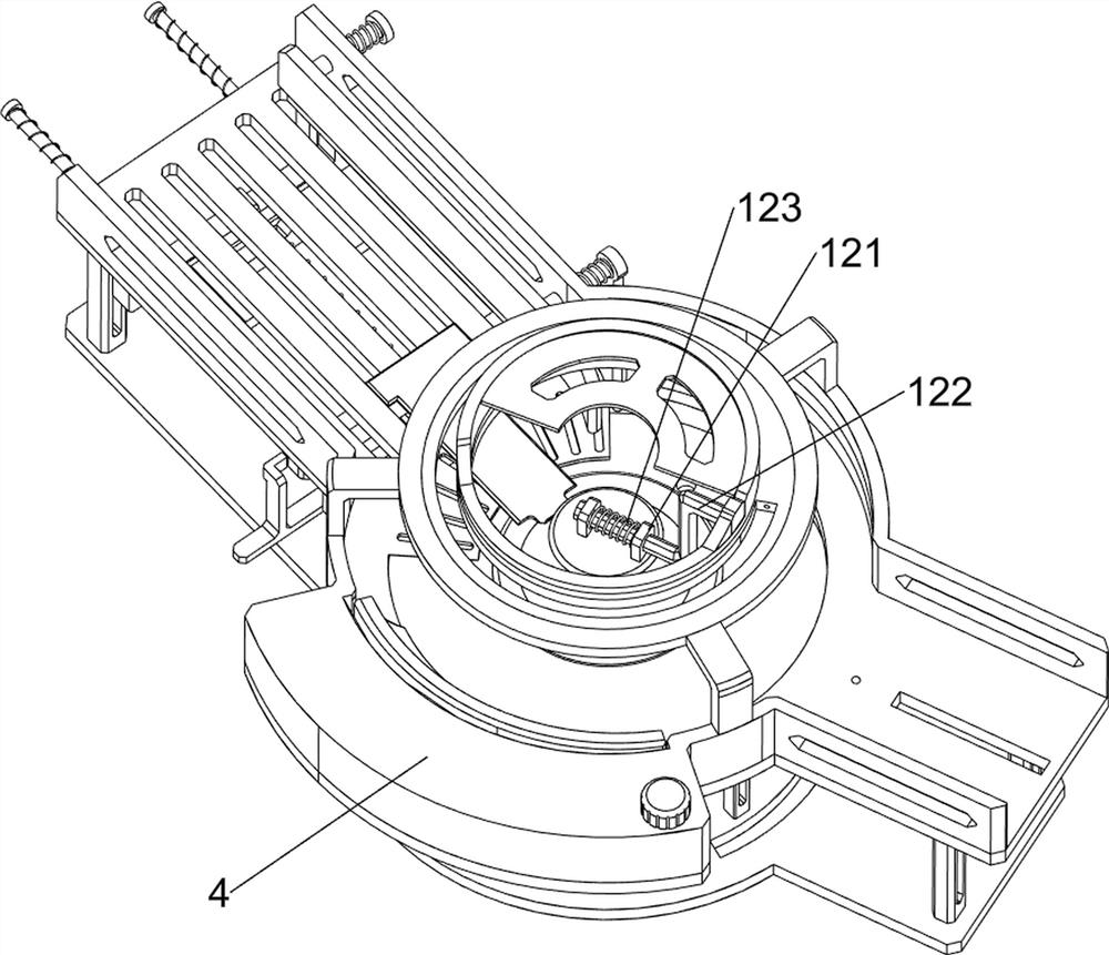
[0090] In a preferred embodiment of the present invention, as Figure 3-Figure 7 As shown, the limit mechanism 9 includes a second support frame 91, a first movable rod 92, a second movable rod 93, a first movable block 94, a third compression spring 95, a heating tube 96 and a fourth compression spring 97. A support frame 1 top middle is provided with the second support frame 91, and the second support frame 91 top sliding type is provided with the first movable rod 92, and the sliding type on the first movable rod 92 is provided with the second movable rod 93, and the second movable rod 93 front and rear sides are slidingly provided with a first movable block 94, a third compression spring 95 is connected between the first movable block 94 and the second movable rod 93, and a heating pipe 96 is uniformly arranged in the lower part of the second support frame 91, There are four heating tubes 96 , a fourth compression spring 97 is connected between the first movable rod 92 and...
Embodiment 3
[0095] In a preferred embodiment of the present invention, as Figure 8-Figure 13 As shown, a pusher mechanism 11 is also included, and the pusher mechanism 11 includes a second support column 111, a screw mandrel 112, a third movable rod 113, a third rotating shaft 114, a first bevel gear set 115 and a first belt 116, The lower part on the left side of the first support frame 1 is provided with two second support columns 111 at intervals, and a screw rod 112 is screwed between the lower parts of the two second support columns 111, and a third movable rod 113 is slidably connected to the screw rod 112 The lower part of the left side of the first support frame 1 is rotatably provided with a third rotating shaft 114, the first bevel gear set 115 is installed between the middle part of the third rotating shaft 114 and the right side of the screw mandrel 112, and the third rotating shaft 114 bottom is connected with the first rotating shaft 103 A first belt 116 is wound between th...
PUM
 Abstract
Description
Claims
Application Information
 - R&D
- Intellectual Property
- Life Sciences
- Materials
- Tech Scout
- Unparalleled Data Quality
- Higher Quality Content
- 60% Fewer Hallucinations
Browse by: Latest US Patents, China's latest patents, Technical Efficacy Thesaurus, Application Domain, Technology Topic, Popular Technical Reports.
© 2025 PatSnap. All rights reserved.Legal|Privacy policy|Modern Slavery Act Transparency Statement|Sitemap|About US| Contact US: help@patsnap.com


