Glazing equipment for sanitary ware

A technology of spraying glaze and sanitary ware, which is applied in the field of ceramic processing, and can solve problems such as easy occurrence of defective products, high labor intensity of operators, easy uneven glazing, etc., and achieve the effect of easy spraying

Active Publication Date: 2020-03-24
CHONGQING CONCAST SANITARY WARE
View PDF5 Cites 0 Cited by
  • Summary
  • Abstract
  • Description
  • Claims
  • Application Information

AI Technical Summary

Problems solved by technology

[0003] It is common to separate the floating material removal operation, the water spraying operation on the surface of the embryo body and the glazing operation. It is necessary to process the embryo body three times in sequence, which is time-consuming and laborious; at the same time, the traditional method of spraying glaze is to manually use a spray gun to glaze, The operation is simple, but the labor intensity of the workers is high, the production efficiency is low, the product quality is low, and defective products are prone to appear, and the common ceramic sanitary ware is large in size, and the glazed surface is many and wide, and it is extremely easy to be glazed unevenly

Method used


Image

  • Glazing equipment for sanitary ware
  • Glazing equipment for sanitary ware
  • Glazing equipment for sanitary ware

Examples


Embodiment Construction

[0016] Further detailed explanation through specific implementation mode below:

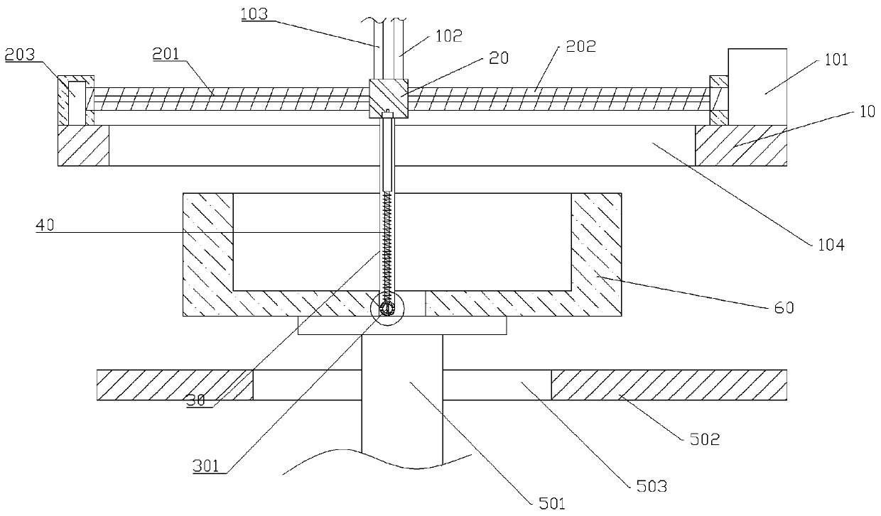
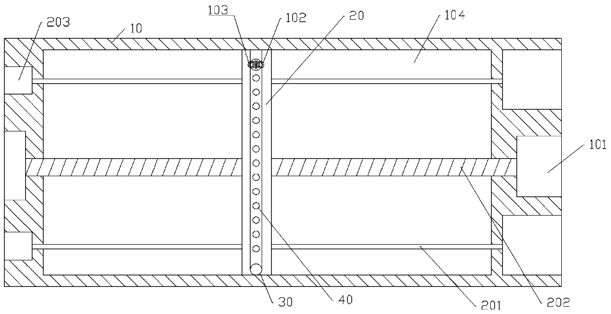
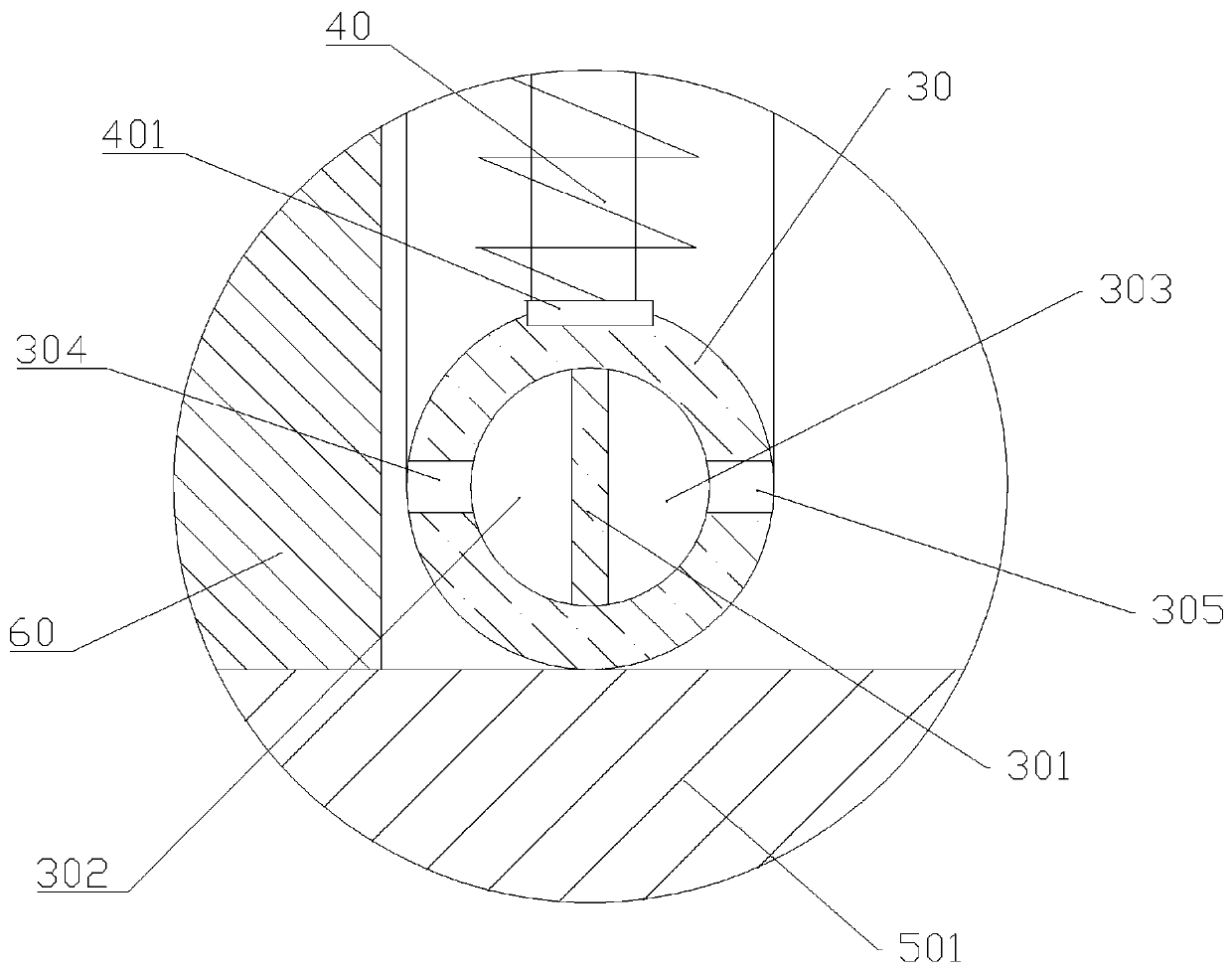
[0017] The reference signs in the accompanying drawings of the description include: mounting plate 10, motor 101, suction pipe 102, glaze spraying pipe 103, vertical through groove 104, moving block 20, sliding rod 201, threaded rod 202, support frame 203, processing Pipe 30, partition bar 301, glaze spray chamber 302, cleaning chamber 303, first through hole 304, second through hole 305, spring rod 40, support plate 401, lifting cylinder 501, conveyor belt 502, processing hole 503, embryo body 60 .

[0018] The embodiment is basically as attached figure 1 , attached figure 2 , attached image 3 And attached Figure 4 Shown: the glaze spraying equipment used for sanitary ware, including a mounting plate 10, a motor 101, a negative pressure pump, a suction pipe 102, a water spray pump, a transmission and pressure mechanism, a processing mechanism and a guiding mechanism. The motor 101 is weld...


PUM


Abstract

The invention relates to the field of ceramic processing, in particular to glaze spraying equipment for sanitary appliances. The glaze spraying equipment comprises a conveying abutting mechanism, a processing mechanism and a guide mechanism, wherein the processing mechanism comprises a flexible processing pipe and a plurality of spring rods, one end of the processing pipe is fixedly connected to one end of a moving block, the other end of the processing pipe is fixedly connected to the other end of the moving block, the lower ends of the spring rods are fixedly connected to the side surface ofthe processing pipe, the spring rods and the processing pipe are located on the same vertical plane, a flexible dividing strip is vertically and fixedly arranged in the processing pipe, one side of the dividing strip and the inner wall of the processing pipe define a glaze spraying cavity, the other side of the dividing strip and the inner wall of the processing pipe define a dust collection andwatering cleaning cavity, a first through hole communicating with the glaze spraying cavity is formed in the processing pipe, and a second through hole communicating with the cleaning cavity is formedin the processing pipe. According to the scheme of the glaze spraying equipment, the consistency of floating material removing operation, water spraying operation on the surfaces of blanks and glazing operation can be improved, and the processing efficiency of the ceramic sanitary appliances can be improved.

Description

technical field [0001] The invention belongs to the field of ceramic processing, and in particular relates to glaze spraying equipment for sanitary ware. Background technique [0002] Common ceramic sanitary ware are all formed in one piece. The production process is to mix the embryo body into mud, then inject the mud into the mold, and then demould. After demoulding, the embryo body is punched or the excess blank is removed Fill holes; then polish the surface of the embryo body to remove some floating material on the surface of the embryo body; After glazing, the fired embryo body is easy to crack. [0003] It is common to separate the floating material removal operation, the water spraying operation on the embryo body surface, and the glazing operation. It is necessary to process the embryo body three times in sequence, which is time-consuming and laborious; at the same time, the traditional glaze spraying method is manual glazing with a spray gun. The operation is simp...

Claims


Application Information

Patent Timeline
Patent Type & Authority Patents(China)
IPC IPC(8): B28B11/04B28B11/22B28B11/00
CPCB28B11/00B28B11/044B28B11/048B28B11/22
Inventor 李林唐其云罗永德
Owner CHONGQING CONCAST SANITARY WARE
Why Eureka
Try Eureka