Lifting positioning device for new energy automobile maintenance

A new energy vehicle, lifting and positioning technology, applied in the direction of lifting devices, lifting frames, etc., can solve the problems of large space occupation in maintenance workshops, large lifting devices, and easy to shake, etc., to achieve small space occupation, small structure size, and convenience The effect of maintenance

Pending Publication Date: 2022-02-01
XIAN AERONAUTICAL UNIV
7 Cites 2 Cited by

AI-Extracted Technical Summary

Problems solved by technology

[0005] The maintenance and lifting device in the prior art also has the following disadvantages in actual use: the existing lifting device has a large size, so it takes up a lot of space in the maintenance workshop, and it is impossible to realize convenient liftin...

Method used

Two driving frames all comprise a median frame 1, and the two ends of median frame 1 are all symmetrically installed with wedge-shaped frame 2; Part, the vehic...

Abstract

The invention discloses a lifting positioning device for new energy automobile maintenance, and belongs to the field of automobile maintenance, the lifting positioning device comprises two travelling frames arranged in parallel, the two travelling frames are jointly provided with two guide rails, the two guide rails are connected and fixed through a connecting frame, and the guide rails are provided with first adjusting mechanisms; the travelling cranes are slidably mounted on the guide rails through the first adjusting mechanisms, two hydraulic rods are symmetrically mounted in the middle of the travelling frames, second adjusting mechanisms are arranged in the travelling frames, the hydraulic rods are mounted on the second adjusting mechanisms, and storage grooves corresponding to the hydraulic rods are formed in the middles of the travelling frames; and the hydraulic rods are stored in the travelling frames through the storage grooves. By adjusting the distance between the travelling frames and the positions of the hydraulic rods, lifting of different automobile types can be achieved, after lifting, automobiles are placed stably, safety is high, and it is convenient for workers to carry out maintenance.

Application Domain

Lifting frames

Technology Topic

EngineeringStructural engineering +2

Image

  • Lifting positioning device for new energy automobile maintenance
  • Lifting positioning device for new energy automobile maintenance
  • Lifting positioning device for new energy automobile maintenance

Examples

  • Experimental program(1)

Example Embodiment

[0032] The technical solutions in the embodiments of the present invention will be clearly and completely described below with reference to the accompanying drawings in the embodiments of the present invention. Obviously, the described embodiments are only a part of the embodiments of the present invention, but not all of the embodiments.
[0033] In the description of the present invention, it should be understood that the terms "upper", "lower", "front", "rear", "left", "right", "top", "bottom", "inside", " The orientation or positional relationship indicated by "outside" is based on the orientation or positional relationship shown in the accompanying drawings, and is only for the convenience of describing the present invention and simplifying the description, rather than indicating or implying that the indicated device or element must have a specific orientation, so as to The specific orientation configuration and operation are therefore not to be construed as limitations of the present invention.
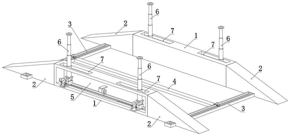
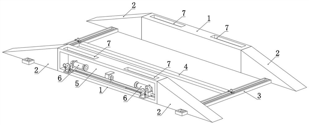
[0034] refer to Figure 1-8 , a lifting and positioning device for maintenance of new energy vehicles, comprising two running frames arranged in parallel, two guide rails 3 are installed together on the two running frames, the two guide rails 3 are connected and fixed by a connecting frame 4, and the guide rail 3 is provided with The first adjustment mechanism, the travel frame is slidably installed with the guide rail 3 through the first adjustment mechanism, two hydraulic rods 6 are symmetrically installed in the middle of the travel frame, and a second adjustment mechanism is arranged in the travel frame. The two adjustment mechanisms are installed, and a storage groove 7 corresponding to the hydraulic rod 6 is opened in the middle of the travel frame, and the hydraulic rod 6 is stored into the interior of the travel frame through the storage groove 7 . A rubber pad is installed on the telescopic end of the hydraulic rod 6 .
[0035] During maintenance, the vehicle is driven on two carriages, and the hydraulic rod 6 is used to lift the vehicle, so that it is convenient for personnel to pass through the maintenance space and to maintain the bottom of the vehicle.
[0036] Both travel frames include a middle frame 1, and both ends of the middle frame 1 are symmetrically installed with wedge frames 2; the wedge frames 2 are arranged according to the figure 1 and 2 The way in the middle is arranged at the end of the middle frame 1, and the vehicle can be conveniently placed on the middle frame 1 through the wedge frame 2, which is convenient for the subsequent use of the hydraulic rod 6 to lift the vehicle.
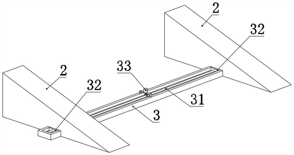
[0037] The top surface of the guide rail 3 is provided with a groove, and the first adjustment mechanism includes a first bidirectional screw rod 31 rotatably installed in the groove. The bottom of the wedge frame 2 is fixedly installed, the first two-way screw rod 31 is driven by a first adjusting motor 33; the first adjusting motor 33 is installed on the upper side of the guide rail 3 through a bracket, and a bevel gear 34 is installed in the middle of the first two-way screw rod 31 , the driving end of the first regulating motor 33 is also installed with a bevel gear 34, and the two bevel gears 34 are meshed with each other. The bottom wall of the wedge frame 2 is provided with a through groove matching the guide rail 3, and the slider 32 is fixed in the through groove.
[0038] According to the specific vehicle model, the distance between the two carriages is adjusted by the first adjustment mechanism. The adjustment process is as follows: the first adjustment motor 33 drives the two bevel gears 34 to mesh with each other, thereby controlling the first bidirectional screw 31 to rotate, and the first adjustment motor 33 drives the two bevel gears 34 to mesh with each other. The bidirectional screw rod 31 and the slider 32 are threadedly installed, and the threaded block 32 is fixed to the bottom of the wedge frame 2. Therefore, when the first bidirectional screw rod 31 rotates, the wedge frame 2 and the entire travel frame can be controlled to move, thereby realizing driving. Shelf spacing adjustment.
[0039] The intermediate frame 1 is provided with a cavity 5, and the second adjustment mechanism includes a second bidirectional screw rod 8 rotatably installed inside the cavity 5. The second bidirectional screw rod 8 is driven by a second adjustment motor 17, and the second bidirectional screw rod 8 A sliding seat 9 is installed with symmetrical threads on both ends of the sliding seat 9, a rotating seat 10 is hingedly installed on the upper side of the sliding seat 9, the hydraulic rod 6 is fixed on the top of the rotating seat 10, and the rotating seat 10 is hingedly installed with the sliding seat 9 through the rotating shaft. A worm wheel 11 is installed, a horizontal plate is installed on the outer side of the sliding seat 9 , and a worm 12 is rotatably installed on the horizontal plate.
[0040] A linkage rod is installed between the two worms 12 on one side of the same intermediate frame 1. The linkage rod has a square tube 16 and two square rods 15. Both ends of the square tube 16 are slidably installed with the square rods 15. One end of the square rod 15 away from the square tube 16 is mounted and fixed to the roller shaft of the worm 12, a first gear 14 is installed between one of the square rods 15 and the worm 12, and the first gear 14 is also installed on the driving end of the rotating motor 13, and the two are installed. The first gears 14 mesh with each other.
[0041] The intermediate frame 1 is provided with a chute at the lower side of the cavity 5 , and the bottom of the sliding seat 9 is provided with a sliding bar matching the chute.
[0042] The second adjusting motor 17 is installed inside the cavity 5, and the second gear 18 is installed at the driving end of the second adjusting motor 17, and the second gear 18 is also installed in the middle of the second bidirectional screw 8. Two second gears 18 mesh with each other.
[0043] Adjust the distance between the two hydraulic rods 6 in each intermediate frame 1 according to the specific vehicle model. The adjustment process is as follows: the second adjustment motor 17 drives the two second gears 18 to mesh with each other, controls the second bidirectional screw 8 to rotate, and the second The two-way screw 8 is threadedly installed with the two sliding seats 9, so the sliding seats 9 can be controlled to approach or move away from each other, thereby controlling the rotating seat 10 and the hydraulic rod 6 to adjust the position, so that the distance between the two hydraulic rods 6 can be adjusted according to the vehicle model. suitable location.
[0044] After the position of the hydraulic rod 6 is appropriate, it needs to be rotated so that its telescopic end can be vertically telescopic, so as to lift the vehicle.
[0045] The rotation process of the hydraulic rod 6 is as follows: the rotary motor 13 drives the two first gears 14 to mesh with each other, controls the worm 12, the square rod 15, and the square tube 16 to rotate at the same time, the worm 12 and the worm wheel 11 mesh with each other, and the rotating seat can be controlled by the rotating shaft 10 and the hydraulic rod 6 are rotated so that the hydraulic rod 16 can be rotated to Image 6 state, the hydraulic rod 6 can be extended to figure 1 state in order to jack up the vehicle.
[0046] The two worms 12 are linked by a linkage rod composed of a square tube 16 and two square rods 15, that is, when one worm 12 rotates, the worm 12 on the other side can also rotate, and the sliding seat 9, the rotating seat 10 and the hydraulic When the position of the rod 6 is adjusted, the sliding cooperation between the square rod 15 and the square tube 16 is used to make the linkage rod retractable and maintain the linkage effect of the two worms 12 .
[0047] The above description is only a preferred embodiment of the present invention, but the protection scope of the present invention is not limited to this. The equivalent replacement or change of the inventive concept thereof shall be included within the protection scope of the present invention.

PUM

no PUM

Description & Claims & Application Information

We can also present the details of the Description, Claims and Application information to help users get a comprehensive understanding of the technical details of the patent, such as background art, summary of invention, brief description of drawings, description of embodiments, and other original content. On the other hand, users can also determine the specific scope of protection of the technology through the list of claims; as well as understand the changes in the life cycle of the technology with the presentation of the patent timeline. Login to view more.

Similar technology patents

Air flue assembly

PendingCN107940709ASimple installation structuresmall structure
Owner:CHINA YANGZI GRP CHUZHOU YANGZI AIR CONDITIONERCO

Magnetoelectric absolute type encoder for planetary gear structure

PendingCN107782342ASmall structureReduce gear transmission errors
Owner:CHANGCHUN SHENGHAO ELECTRONICS

Classification and recommendation of technical efficacy words

  • Reduce space consumption
  • small structure

Mobile terminal

PendingCN110620834AReduce space consumption
Owner:SHENZHEN TRANSSION HLDG CO LTD

Folding device for double pieces of corrugated paper

Owner:BEIJING INSTITUTE OF GRAPHIC COMMUNICATION

Balance vehicle wheel fixing structure and balance vehicle

ActiveCN106005161AReduce space consumption
Owner:深圳市骜途智能科技有限公司

STL-based 3D printed file data processing method

InactiveCN109551768AData processing is simpleReduce space consumption
Owner:GUANGXI POWER GRID ELECTRIC POWER RES INST
Why Eureka
Try Eureka