Device and method for detecting oil level of oil conservator of transformer
A technology of oil level detection and transformer oil, which is applied in the direction of displaying liquid level indicators through pressure measurement, can solve the problems of high operation risk and inaccurate measurement of running time, achieve accurate oil level detection, improve detection accuracy, Life-enhancing effect
- Summary
- Abstract
- Description
- Claims
- Application Information
AI Technical Summary
Problems solved by technology
Method used
Image
Examples
Embodiment 1
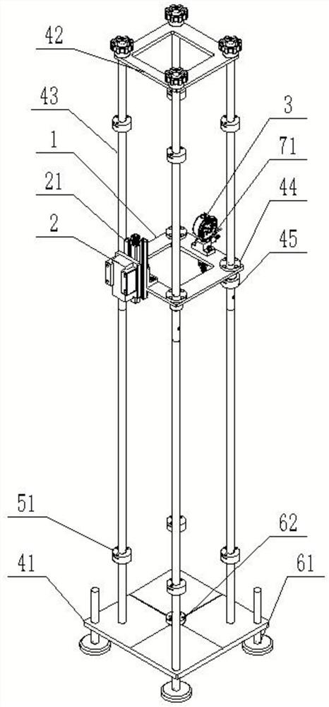
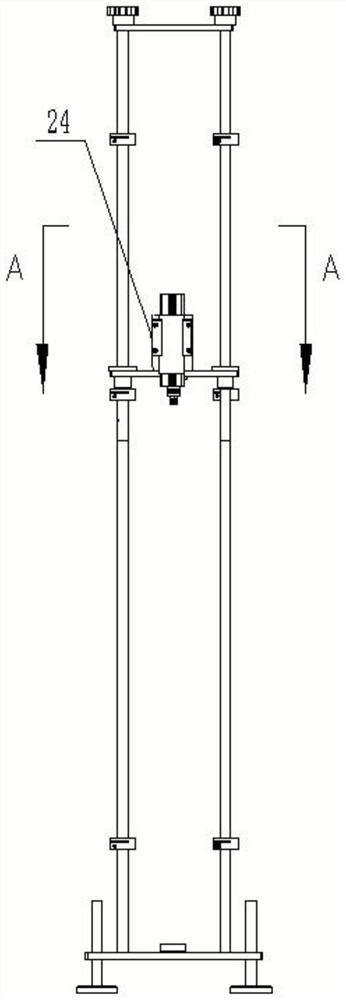
[0028] Such as figure 1 As shown, a transformer oil conservator oil level detection device includes: a bracket, an adjustment plate 1, a laser ruler 2, and a pressure gauge 3; an adjustment plate 1 is set on the bracket, and the adjustment plate 1 is slidingly connected with the bracket; The ruler 2 is arranged on one side of the top of the adjustment plate 1, and the laser ruler 2 is connected with the adjustment plate 1; the pressure gauge 3 is arranged on the other side of the top of the adjustment plate 1, and the pressure gauge 3 is connected with the adjustment plate 1, The pressure gauge 3 is connected to the oil conservator of the transformer to be tested through a hose, and the laser ruler is used in conjunction with the pressure gauge to obtain the pressure of the pressure gauge at different positions from the oil conservator of the transformer to be tested, which can be directly measured and obtained through different pressures and distances The liquid level of the ...
Embodiment 2
[0030] A detection method of a transformer oil conservator oil level detection device, comprising the following steps:
[0031] S1. Place the bracket under the oil conservator under test, and adjust the height of each adjustment foot 61 according to the level bubble 62, so that the base 41 is level;
[0032] S2. Turn on the laser ruler 2 and adjust the position of the bracket so that the indication point of the laser ruler 2 is at the lowest point of the oil conservator;
[0033] S3. Connect the end of the hose far away from the quick connector 72 to the valve of the oil conservator to be tested. After opening the valve on the oil conservator, open the valve 73 on the tee 71. After the oil flowing out of the valve 73 is stable and free of air bubbles, Close valve 73 and the valve of the oil conservator under test;
[0034] S4. Disconnect the hose from the valve of the oil conservator under test, hold the end of the hose far away from the quick connector 72 above the pressure ...
Embodiment 3
[0040] In order to further improve the accuracy of detection, the quick connectors, pressure gauges and valves connected through the three-way connection can not only quickly connect the hose, but also discharge the gas inside the hose to prevent the gas from affecting the measurement results.
[0041] Such as image 3 , 4 As shown, preferably, a tee 71 is fixed on the top of the side of the adjustment plate 1 close to the pressure gauge 3, the pressure gauge 3 is located directly above the tee 71 and communicates with it, and the adjustment plate 1 is located directly below the tee 71 and also A quick joint 72 is provided, and one end of the quick joint 72 passes through the adjustment plate 1 to communicate with the tee 71, and the other end of the quick joint 72 is detachably connected with the hose. The outside of the adjustment plate 1 is also provided with a valve 73, which is connected to the three Through 71 communication, the quick connectors, pressure gauges and valve...
PUM
 Abstract
Description
Claims
Application Information
 - R&D
- Intellectual Property
- Life Sciences
- Materials
- Tech Scout
- Unparalleled Data Quality
- Higher Quality Content
- 60% Fewer Hallucinations
Browse by: Latest US Patents, China's latest patents, Technical Efficacy Thesaurus, Application Domain, Technology Topic, Popular Technical Reports.
© 2025 PatSnap. All rights reserved.Legal|Privacy policy|Modern Slavery Act Transparency Statement|Sitemap|About US| Contact US: help@patsnap.com


