Head band adjusting device and head-mounted equipment

A technology for adjusting devices and headbands, applied in optical components, optics, instruments, etc., can solve the problems that hinder the miniaturization, light weight, complex structure, and heavy weight of head-mounted equipment, and achieve light weight, small volume, and simple structure Effect

Active Publication Date: 2022-02-01
QINGDAO GOERTEK
View PDF5 Cites 0 Cited by
  • Summary
  • Abstract
  • Description
  • Claims
  • Application Information

AI Technical Summary

Problems solved by technology

In order to meet the needs of different users and improve wearing comfort, existing head-mounted devices are usually equipped with headband adjustment devices. Development in the direction of miniaturization and lightweight

Method used


Image

  • Head band adjusting device and head-mounted equipment
  • Head band adjusting device and head-mounted equipment
  • Head band adjusting device and head-mounted equipment

Examples


Embodiment 1

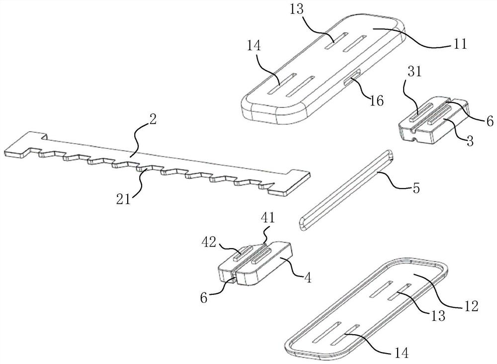
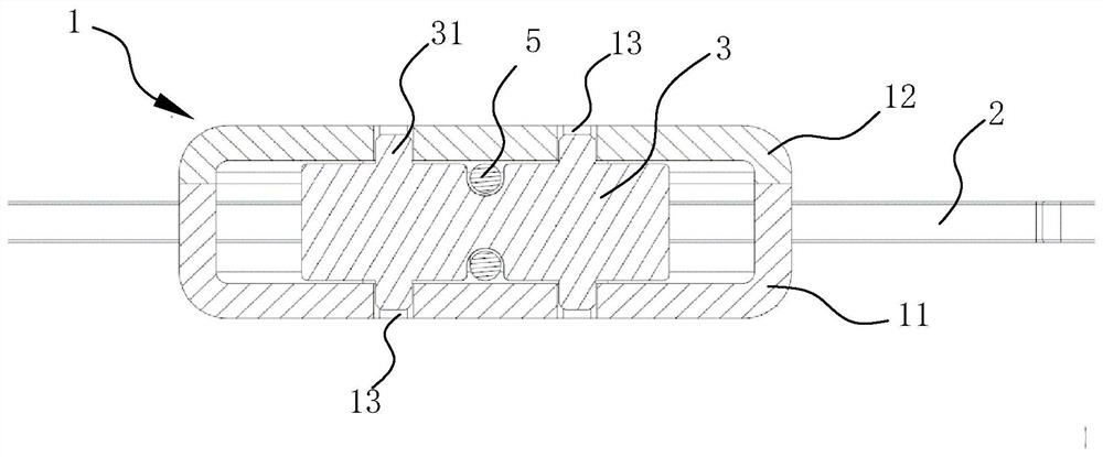
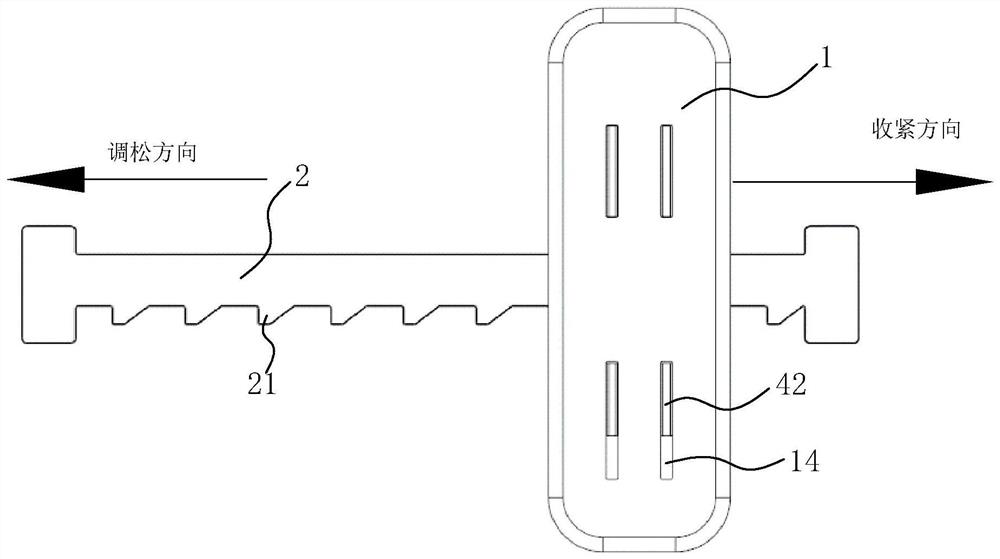
[0039] Depend on Figure 1 to Figure 3 Commonly shown, this embodiment discloses a headband adjustment device; it includes a housing 1, an adjustment belt 2, a limit stopper 3 fixed in the housing 1, and is slidably installed in the direction toward or away from the limit stopper 3. The sliding block 4 and the elastic reset member in the housing 1; the extension direction of the adjustment belt 2 is perpendicular to the sliding direction of the sliding block 4, and the adjustment belt 2 is partly inserted between the limit block 3 and the sliding block 4 The adjustment belt 2 is provided with a ratchet bar part 21 on the side facing the sliding block 4, and the side of the sliding block 4 facing the adjustment belt 2 is formed with a one-way lock for engaging with the ratchet bar part 21 to realize one-way locking The stopper 41; the elastic reset member is used to provide an elastic reset force, and under the action of the elastic reset force, the sliding block 4 moves toward...

Embodiment 2

[0051] The structure and principle of the second embodiment are basically the same as those of the first embodiment, except that the structure of the elastic reset member is different; only the differences will be described below.

[0052] Depend on Figure 8 to Figure 11 Commonly shown, the elastic reset member in this embodiment is a cylindrical spring 7; the cylindrical spring 7 is contained in the housing 1 (see figure 2 ), one end is in contact with the inner wall of the housing 1, and the other end is in contact with the side of the sliding block 4 away from the adjustment belt 2.

[0053] In order to prevent the cylindrical spring 7 from twisting and deforming and affecting the locking accuracy, this embodiment optimizes the above-mentioned structure, and the inner wall of the housing 1 (the second housing 12 can also be on the first housing 11) is provided with The spring mounting seat 15 and the side of the sliding block 4 facing away from the adjusting belt 2 are p...


PUM


Abstract

The invention discloses a head band adjusting device and head-mounted equipment. The head band adjusting device comprises a shell, an adjusting band, a limiting stop block fixed in the shell, a sliding stop block which is installed in the shell in a sliding mode towards or away from the direction of the limiting stop block, and an elastic reset piece. The extending direction of the adjusting band is perpendicular to the sliding direction of the sliding stop block, the adjusting band is partially arranged between the limiting stop block and the sliding stop block in a penetrating mode, a ratchet bar part is arranged at the side, facing the sliding stop block, of the adjusting band and a one-way locking part used for being meshed with the ratchet bar part to achieve one-way locking is formed at the side, facing the adjusting band, of the sliding stop block; the elastic reset piece is used for providing elastic reset force, and under the effect of the elastic reset force, the sliding stop block moves towards the limiting stop block so as to achieve meshing of the one-way locking part and the ratchet bar part. The head-mounted equipment comprises the head band adjusting device. The head band adjusting device is simple in structure, small in size and light in weight, and development of the head-mounted device towards the miniaturization and light weight direction is facilitated.

Description

technical field [0001] The invention belongs to the technical field of head-mounted equipment, and in particular relates to a headband adjusting device and a head-mounted device. Background technique [0002] In recent years, with the advancement of technology, virtual reality (VR, Virtual Reality) and augmented reality (AR, Augmented Reality) technologies have gradually been accepted by users and the market, and have become another engine driving technological innovation and display technology innovation. [0003] In the existing technologies, VR and AR technologies are generally implemented on the basis of head-mounted devices. In order to meet the needs of different users and improve wearing comfort, existing head-mounted devices are usually equipped with headband adjustment devices. Development in the direction of miniaturization and lightweight. Contents of the invention [0004] In order to overcome the above-mentioned problems in the prior art, the object of the p...

Claims


Application Information

Patent Timeline
Patent Type & Authority Applications(China)
IPC IPC(8): G02B27/01
CPCG02B27/0176
Inventor 米波李德华杜志元
Owner QINGDAO GOERTEK
Why Eureka
Try Eureka