Method for adjusting rotational inertia of inertia friction welding

A friction welding and moment of inertia technology, applied in the field of inertia friction welding, can solve the problems of equipment accuracy and dynamic balance damage, major damage to the spindle and drive motor, and inability to meet welding needs, reducing welding quality and ensuring continuity and smoothness. performance, ensuring welding efficiency and welding quality

Active Publication Date: 2022-02-08
NO 59 RES INST OF CHINA ORDNANCE IND
View PDF7 Cites 0 Cited by
  • Summary
  • Abstract
  • Description
  • Claims
  • Application Information

AI Technical Summary

Problems solved by technology

[0003] However, in the existing inertial friction welding method, according to different inertial or energy requirements, it is necessary to adjust the speed. In addition to the speed adjustment, the flywheel needs to be replaced. Frequent replacement of the flywheel will waste production time and reduce production efficiency. The second is that repeated loading and unloading of the flywheel will cause damage to the accuracy of the equipment (that is, coaxiality and other parameters) and dynamic balance, and it needs to be re-calibrated, which further wastes production time; Further realize the adjustment of the friction speed (that is, the friction welding can only be realized according to the predetermined reduced speed), and some special welding needs cannot be realized; moreover, the inertia friction welding method of the prior art needs to stop the welding process immediately for sudden or special situations , the shutdown speed is slow, the damage to the spindle and drive motor is large, the equipment is aging quickly, and the process cost is high

Method used


Image

  • Method for adjusting rotational inertia of inertia friction welding
  • Method for adjusting rotational inertia of inertia friction welding
  • Method for adjusting rotational inertia of inertia friction welding

Examples


Embodiment

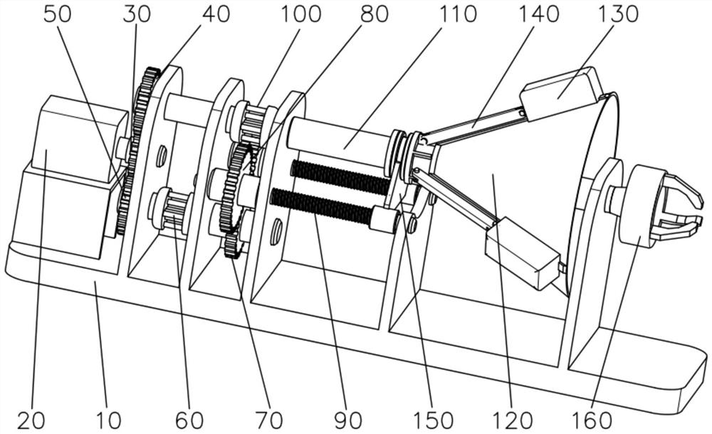
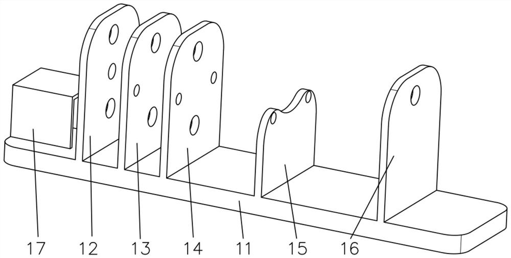
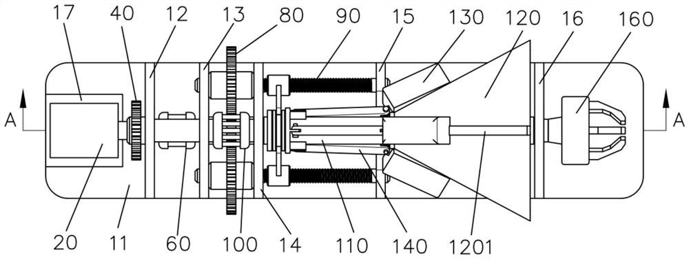
[0038] Such as Figure 1-8 As shown, a method for adjusting the moment of inertia of inertial friction welding is characterized in that: a flywheel adjustment device is used for welding, and the flywheel adjustment device includes a device body 10, a drive motor 20, a first gear 30, a second gear 40, and a second gear 40. Three gears 50, lead screw clutch 60, fourth gear 70, fifth gear 80, lead screw 90, main shaft clutch 100, main shaft 110, conical flywheel disc 120, mass slider 130, connecting rod 140 and connecting member 150; device The body 10 includes a supporting platform 11, a gear bracket 12, a clutch bracket 13, a rotating shaft bracket 14, a screw bracket 15 and a main shaft bracket 16; the upper end surface of the supporting platform 11 is from left to right (such as figure 1 , figure 2 As shown), the gear bracket 12, the clutch bracket 13, the rotating shaft bracket 14, the screw bracket 15 and the main shaft bracket 16 are fixedly arranged in sequence; the out...


PUM


Abstract

The invention provides a method for adjusting the rotational inertia of inertia friction welding. The method comprises the steps of a, initial state correction and b, inertia friction welding. The inertia friction welding comprises the sub-steps of b1, conducting flywheel rotational inertia adjustment; and b2, conducting inertia friction welding on a workpiece to be welded. The method adopts a flywheel adjusting device which comprises a device body (10), a driving motor (20), a first gear (30), a second gear (40), a third gear (50), a lead screw clutch (60), a fourth gear (70), a fifth gear (80), a lead screw (90), a main shaft clutch (100), a main shaft (110), a conical flywheel disc (120), a mass sliding block (130), a connecting rod (140) and a connecting component (150). According to the method, according to different inertia or energy requirements in friction welding, the flywheel does not need to be frequently replaced, the precision and dynamic balance do not need to be corrected again after the flywheel is replaced, and then rotational inertia adjustment is achieved.

Description

technical field [0001] The invention relates to the technical field of inertial friction welding, in particular to a method for adjusting the moment of inertia of inertial friction welding. Background technique [0002] Friction welding is currently one of the main welding methods for connecting axisymmetric parts such as bars and pipes in the equipment manufacturing industry. For high-alloy steels such as heat-resistant steels, non-ferrous metals such as aluminum alloys, which are difficult to weld by traditional fusion welding methods, materials that are sensitive to heat input, friction welding can successfully achieve homogeneous and heterogeneous welding due to its advantages such as low heat input and solid phase welding. effective connection between metals. Friction welding includes continuous drive friction welding and inertia friction welding; continuous drive friction welding makes the heat input on the friction surface of the workpiece continuous and constant thr...

Claims


Application Information

Patent Timeline
Patent Type & Authority Applications(China)
IPC IPC(8): B23K20/12
CPCB23K20/1245B23K20/125
Inventor 陈大军李忠盛吴护林代野刘正涛戴明辉黄俊付扬帆吴厦江波
Owner NO 59 RES INST OF CHINA ORDNANCE IND
Why Eureka
Try Eureka