Hydraulic system of hydraulic aerial cage

A technology for aerial work vehicles and hydraulic systems, which is applied in the direction of fluid pressure actuation system components, fluid pressure actuation devices, lifting devices, etc., and can solve the problems that hydraulic devices do not have cooling and filtering operations, shortened service life, etc., to avoid Uneven water temperature, improved cleanliness, and extended service life

Active Publication Date: 2022-02-08
青岛索尔汽车有限公司
View PDF15 Cites 0 Cited by
  • Summary
  • Abstract
  • Description
  • Claims
  • Application Information

AI Technical Summary

Problems solved by technology

[0004] In view of the above situation, in order to overcome the defects of the prior art, the present invention provides a hydraulic system of an aerial work vehicle, which effectively solves the problem that the hydraulic device of the aerial work vehicle in the above background technology does not have cooling and filtering operations, resulting in shortened service life. question

Method used


Image

  • Hydraulic system of hydraulic aerial cage
  • Hydraulic system of hydraulic aerial cage
  • Hydraulic system of hydraulic aerial cage

Examples


Embodiment 1

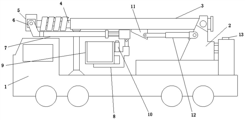
[0031] Embodiment one, by Figure 1 to Figure 6 Given, the present invention includes a work vehicle body 1, a support frame 2 is provided on the top of the work vehicle body 1, a main hydraulic cylinder 3 is movably connected to the top of the support frame 2, and a telescopic rod 4 is connected to the output shaft of the main hydraulic cylinder 3. One end of the rod 4 is connected with a joint 5, and one side of the joint 5 is movably connected with a connecting bracket 6, and one end of the connecting bracket 6 is provided with an insulating oil hydraulic rod 7, and one end of the insulating oil hydraulic rod 7 is connected with a mounting frame 8, and the mounting frame 8 Hanging basket 9 is installed on it, through the design of hanging basket 9, it is convenient to bring convenience to the work of the staff, and the top of the installation frame 8 and the work vehicle body 1 are provided with a fuel tank 10, and the top of the fuel tank 10 is provided with a filtering coo...

Embodiment 2

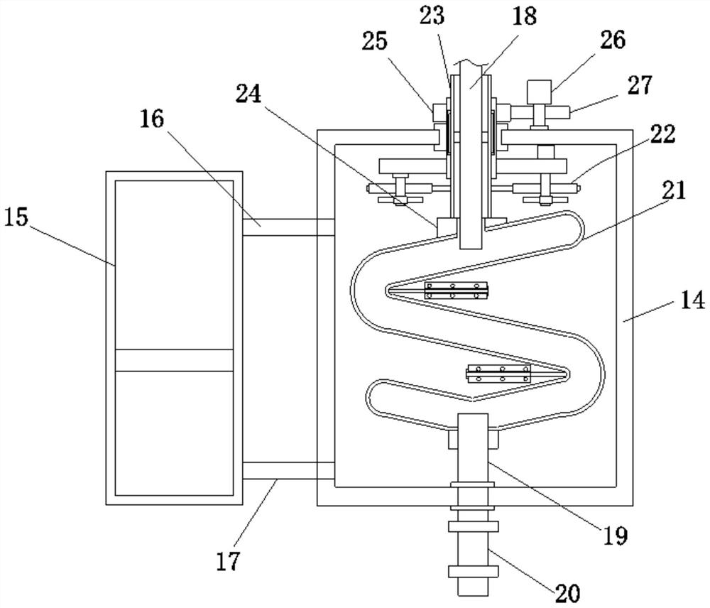
[0033] Embodiment two, on the basis of embodiment one, by figure 2 Given, the outer wall of the cooling pipe 21 is provided with a stirring shaft, and the outside of the stirring shaft is provided with a stirring blade, so as to realize the stirring of the cooling water, avoid the uneven temperature of the cooling water, and thereby accelerate the cooling rate of the oil.

Embodiment 3

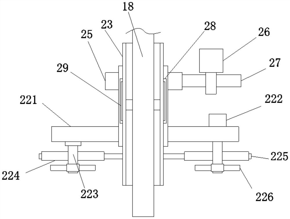
[0034] Embodiment three, on the basis of embodiment one, by figure 2 and image 3 Given, the sleeve 23 is symmetrically provided with a sliding plate 29 , and the inner wall of the collar is provided with a slide groove 28 slidably connected with the sliding plate 29 , so as to realize the protection of the sleeve 23 .


PUM


Abstract

The invention relates to the technical field of high-altitude operation equipment, discloses a hydraulic system of a hydraulic aerial cage, and solves the problem that the service life of a hydraulic device of a hydraulic aerial cage is shortened due to the fact that the hydraulic device of the hydraulic aerial cage does not have cooling and filtering operations. A hydraulic aerial cage body is included; a supporting frame is arranged at the top end of the hydraulic aerial cage body; the top end of the supporting frame is movably connected with a main hydraulic cylinder; an output shaft of the main hydraulic cylinder is connected with a telescopic rod; one end of the telescopic rod is connected with a connector; one side of the connector is movably connected with a connecting support; an insulating oil hydraulic rod is arranged at one end of the connecting support; one end of the insulating oil hydraulic rod is connected with a mounting frame; a hanging basket is mounted on the mounting frame; and oil tanks are arranged at the top ends of the mounting frame and the hydraulic aerial cage body; Through the effect of a filter, impurities in oil are effectively filtered, then the cleanliness of the oil is improved, convenience is brought to work of the main hydraulic cylinder and the insulating oil hydraulic rod, and the service life of the main hydraulic cylinder and the service life of the insulating oil hydraulic rod are effectively prolonged.

Description

technical field [0001] The invention belongs to the technical field of aerial work equipment, in particular to a hydraulic system of an aerial work vehicle. Background technique [0002] Aerial work vehicles have a wide range of applications. Usually, aerial work vehicles include a boom set on the car body and a working bucket or working device installed at the end of the boom. The staff enters the working bucket and uses the boom to move The working bucket and the staff or the working device are sent to a high place for high-altitude operations. [0003] However, the hydraulic device of the existing aerial work vehicle cannot cool and filter the hot oil generated during work, which will cause damage to the hydraulic device of the aerial work vehicle, thereby shortening the service life of the aerial work vehicle. Contents of the invention [0004] In view of the above situation, in order to overcome the defects of the prior art, the present invention provides a hydraulic...

Claims


Application Information

Patent Timeline
Patent Type & Authority Applications(China)
IPC IPC(8): B66F11/04F15B21/041F15B21/0423
CPCB66F11/046F15B21/041F15B21/0423
Inventor 李启江刘维庭曲志龙王军勃姜明山张钦梅小伟韩磊
Owner 青岛索尔汽车有限公司
Why Eureka
Try Eureka