
Connecting structure of assembly type composite floor slab and cast-in-place beam

A technology of superimposed floor slabs and cast-in-place beams, applied to floors, truss structures, building structures, etc., can solve the problems of difficult installation and collision of reserved anchoring steel bars, and achieve reliable mechanical performance, collision avoidance, and rapid hoisting In place effect

Pending Publication Date: 2022-02-08
CISDI ENG CO LTD
View PDF7 Cites 1 Cited by
  • Summary
  • Abstract
  • Description
  • Claims
  • Application Information

AI Technical Summary

Problems solved by technology

[0004] In view of this, the connection structure of this technical solution can realize the rapid hoisting of the superimposed floor slab in place at the construction site, avoid the collision between the reserved anchor reinforcement bars of the superimposed floor slabs and the cast-in-place beams, and solve the problem that the reserved anchor reinforcement bars of the superimposed floor slabs are not easy to install. Difficult problem, due to the setting of longitudinal ribs and ring stirrups at the pick-up ears, there is no need to cut corners at the beam-column joints when dividing the laminated slabs. The laminated floors split by this method are all regular rectangles, which improves Production and construction efficiency ensure reliable mechanical performance of joints between laminated floor slabs and cast-in-place beams

Method used


Image

  • Connecting structure of assembly type composite floor slab and cast-in-place beam

Examples


Embodiment Construction

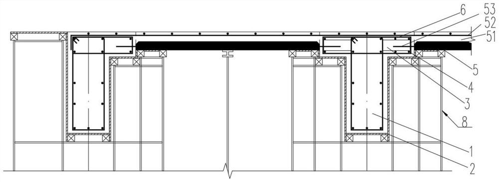
[0014] figure 1 It is a schematic diagram of the overall structure of the present invention; as shown in the figure, a connection structure between an assembled composite floor and cast-in-place beams includes a cast-in-place beam 1 installed in a cast-in-place beam template 2 and a cast-in-place beam 1 connected Laminated floor slab 5; two sides of the cast-in-place beam 1 extend outward to form pick ears 3, and ring-shaped stirrups 6 for use with the laminated floor slab 5 are installed on the pick ears 3. The connection structure of the technical solution , which can realize the rapid hoisting of the laminated floor in place at the construction site, avoiding the collision between the reserved anchoring steel bars of the laminated floor and the cast-in-place beams, and solving the problem that the reserved anchoring steel bars of the laminated floor are not easy to install. With the setting of ring-shaped stirrups, there is no need to cut corners at the beam-column joints w...


PUM


Abstract

The invention discloses a connecting structure of an assembly type composite floor slab and a cast-in-place beam. The connecting structure comprises the cast-in-place beam installed in a cast-in-place beam formwork and the composite floor slab connected with the cast-in-place beam in a pouring mode. The two sides of the cast-in-place beam extend outwards to form lifting lugs, and the lifting lugs are provided with annular stirrups used for being matched with the composite floor slab for use. According to the connecting structure of the technical scheme, the composite floor slab can be rapidly hoisted in place on a construction site, collision between reserved anchoring steel bars of the composite floor slab and cast-in-place beam longitudinal bars and stirrups is avoided, and the problem that the composite floor slab is not easy to install, and the longitudinal steel bars and the annular stirrups are arranged at the lifting lugs is solved, when the composite floor slabs are divided, corner cutting does not need to be carried out at the beam-column connecting positions, the composite floor slabs split through the method are all regular rectangles, the production and construction efficiency of the composite floor slabs is improved, and it is guaranteed that the stress performance of the connecting joints of the composite floor slabs and the cast-in-place beams is reliable.

Description

technical field [0001] The invention relates to the field of building construction, in particular to a connection structure between an assembled composite floor slab and a cast-in-place beam. Background technique [0002] When installing laminated slabs and cast-in-place beams, the traditional method of designing a reinforced laminated slab in a cast-in-place beam system first aligns the laminated slab with the cast-in-place beams. When aligning and installing, it is often because the reserved anchoring steel bars are not easy to be aligned, so a lot of time will be wasted in the alignment and binding of the reserved anchoring steel bars. [0003] Therefore, in order to solve the above problems, there is a need for a connection structure between prefabricated laminated floor slabs and cast-in-place beams to solve the above problems. Contents of the invention [0004] In view of this, the connection structure of this technical solution can realize the rapid hoisting of the...

Claims


Application Information

Patent Timeline
Patent Type & Authority Applications(China)
IPC IPC(8): E04B5/17E04C3/20E04B1/41
CPCE04B5/17E04C3/20E04B1/41
Inventor 杨洋薛尚铃徐革陶修周礼婷余周沈琪雯周代豪
Owner CISDI ENG CO LTD
Learn More