
Medical endoscope testing device and testing method

A technology of a testing device and a cavity mirror, which is applied in the field of cavity mirror testing, can solve problems such as unfavorable working efficiency and reduce the practicability of the testing device, and achieve the effects of improving practicability, improving working efficiency and being convenient to use.

Pending Publication Date: 2022-02-08
苏州科卓医疗科技有限公司
View PDF0 Cites 0 Cited by
  • Summary
  • Abstract
  • Description
  • Claims
  • Application Information

AI Technical Summary

Problems solved by technology

[0004] In view of the deficiencies in the prior art, the purpose of the present invention is to provide a medical laparoscopic testing device and testing method, which solves the problem that the existing testing device can only perform a single test on the laparoscopic lens. After the lens is tested, the lens needs to be transferred to another device for testing, which reduces the practicability of the test device and is not conducive to improving work efficiency

Method used


Image

  • Medical endoscope testing device and testing method
  • Medical endoscope testing device and testing method
  • Medical endoscope testing device and testing method

Examples


Embodiment 1

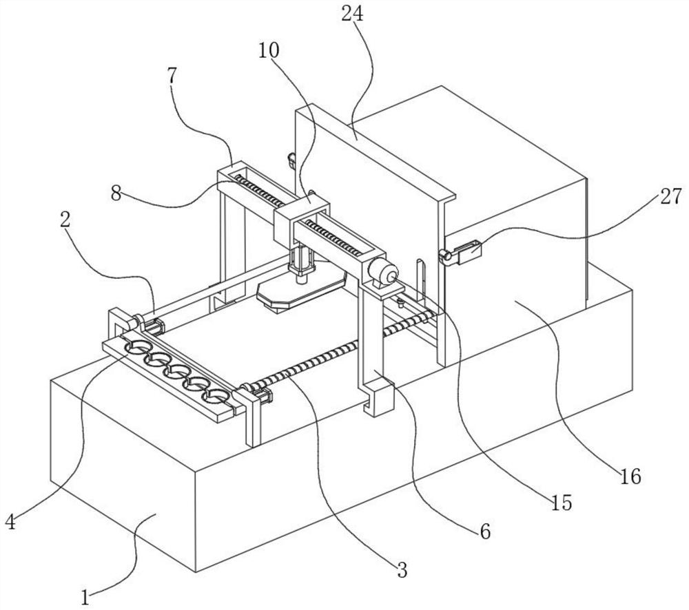
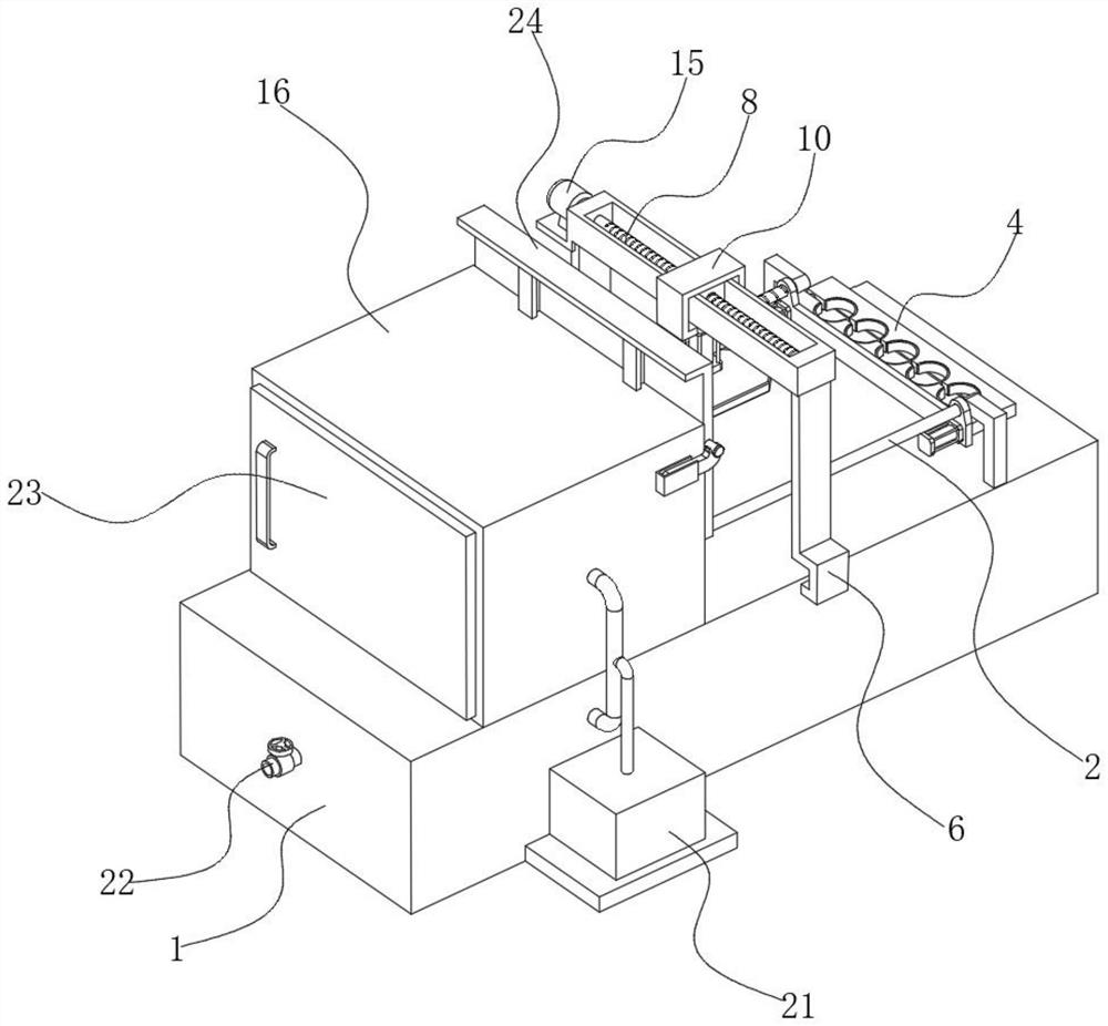
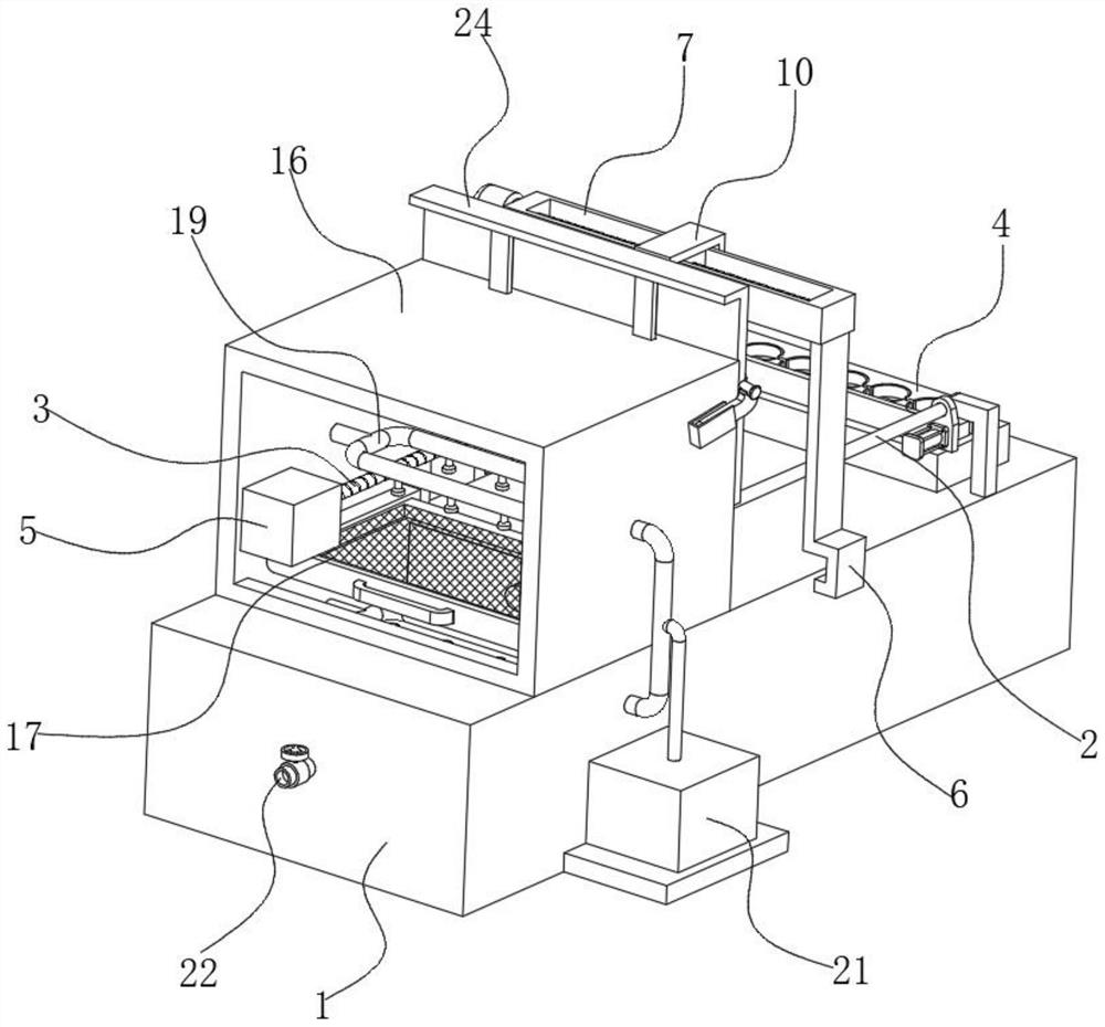
[0038] see Figure 1-9, the present invention provides a technical solution: a medical laparoscopic testing device, including a base 1, a first motor 5 and a second motor 15, one end of the top of the base 1 is fixedly installed with a connecting rod 2, and the top of the base 1 is away from One end of the connecting rod 2 is rotatably connected with a first screw rod 3, the external thread of the first screw rod 3 is connected with a clamping mechanism 4, the top of the front and back of the base 1 is fixedly installed with a bracket 6, and the top of the bracket 6 is fixedly installed There is a frame 7, the inside of the frame 7 is sleeved with a second screw mandrel 8, the driving ends of the first motor 5 and the second motor 15 are fixedly connected with the first screw mandrel 3 and the second screw mandrel 8 respectively, and the second screw mandrel 8 The external thread of the sliding block 9 is connected with the sliding block 9, the top of the sliding block 9 is fi...

Embodiment 2

[0041] Such as Figure 1-9 As shown, on the basis of Embodiment 1, the present invention provides a technical solution: the clamping mechanism 4 includes a fixed clamping plate 401 and a moving clamping plate 402, and the side of the fixed clamping plate 401 away from the moving clamping plate 402 A clamping cylinder 403 is fixedly installed, and the opposite sides of the fixed clamping plate 401 and the movable clamping plate 402 are provided with a clamping groove 404, and a protective pad 405 is fixedly installed inside the clamping groove 404 to clamp the piston rod of the cylinder 403. Fixedly connected with the movable clamping plate 402 , one end of the fixed clamping plate 401 is screwed to the outside of the first screw rod 3 , and the end of the fixed clamping plate 401 away from the first screw rod 3 is sleeved on the outside of the connecting rod 2 .

[0042] In this embodiment, when clamping and fixing the laparoscopic lens, first place the laparoscopic lens one b...

Embodiment 3

[0044] Such as Figure 1-9 As shown, on the basis of Embodiment 1 and Embodiment 2, the present invention provides a technical solution: an installation frame 18 is fixedly installed inside the housing 16, and the two ends of the placement net 17 are respectively slidably installed inside the installation frame 18.

[0045] In this embodiment, the placement net 17 is slidably installed inside the housing 16 through the provided installation frame 18, so that it is convenient for the staff to pull out the placement net 17 and take the laparoscopic lens on the top thereof.


PUM


Abstract

The invention discloses a medical endoscope testing device and method, and the device comprises a base, a first motor and a second motor, the exterior of a first lead screw is in threaded connection with a clamping mechanism, the bottom of a sliding frame is fixedly provided with a lifting cylinder, and one end of the bottom of a mounting plate is fixedly provided with a distance measuring sensor. An ultrasonic sensor is fixedly mounted at the end, away from the distance measuring sensor, of the bottom of the mounting plate, a placement net is slidably mounted in the shell, injection cylinders are fixedly mounted in the base and the shell, atomizing nozzles are fixedly mounted on the opposite sides of the two injection cylinders, and an atomizing mechanism is fixedly mounted at one end of the back face of the base. By arranging a distance measuring sensor, an ultrasonic sensor and an atomizing mechanism, the effect that the laparoscope lens can be subjected to multiple tests in one device is achieved, workers do not need to transfer the laparoscope lens for multiple times, use by the workers is facilitated, the practicability of the testing device is greatly improved, and the working efficiency is improved.

Description

technical field [0001] The invention belongs to the technical field of endoscope testing, and in particular relates to a medical endoscope testing device and a testing method. Background technique [0002] Laparoscopic surgery is a newly developed minimally invasive method, and it is an inevitable trend in the development of future surgical methods. With the rapid development of industrial manufacturing technology, the integration of related disciplines has laid a solid foundation for the development of new technologies and methods. Coupled with the increasingly skilled operation of doctors, many open operations in the past have now been replaced by endovascular surgery. Greatly increased surgical options. Laparoscope is an indispensable medical device in laparoscopic surgery. Laparoscope is similar to electronic gastroscope. It is a medical device with a miniature camera. The lens, light source, camera, monitor, etc. constitute the endoscopic system, which is used to assi...

Claims


Application Information

Patent Timeline
Patent Type & Authority Applications(China)
IPC IPC(8): G01B17/02G01B17/08G01N17/00
CPCG01B17/02G01B17/08G01N17/00
Inventor 林上游周正宇张琦袁娟严爽
Owner 苏州科卓医疗科技有限公司
Learn More