A punching collector ring nozzle device

A technology of collector rings and flushing outlets, applied in metal processing, etc., can solve problems such as damage to products, and achieve the effects of avoiding scratches, reducing replacements, and saving costs

Active Publication Date: 2022-07-22
XUZHOU YUNTAI AUTOMOBILE ELECTRICAL APPLIANCE
View PDF7 Cites 0 Cited by
  • Summary
  • Abstract
  • Description
  • Claims
  • Application Information

AI Technical Summary

Problems solved by technology

[0004] The purpose of the present invention is to provide a punching collector ring nozzle device to solve the problem in the background technology that the straight up and down hard punching damages the product and requires secondary processing

Method used


Image

  • A punching collector ring nozzle device
  • A punching collector ring nozzle device
  • A punching collector ring nozzle device

Examples


Embodiment Construction

[0027] The technical solutions in the embodiments of the present invention will be clearly and completely described below with reference to the accompanying drawings in the embodiments of the present invention. Obviously, the described embodiments are only a part of the embodiments of the present invention, but not all of the embodiments. Based on the embodiments of the present invention, all other embodiments obtained by those of ordinary skill in the art without creative efforts shall fall within the protection scope of the present invention.

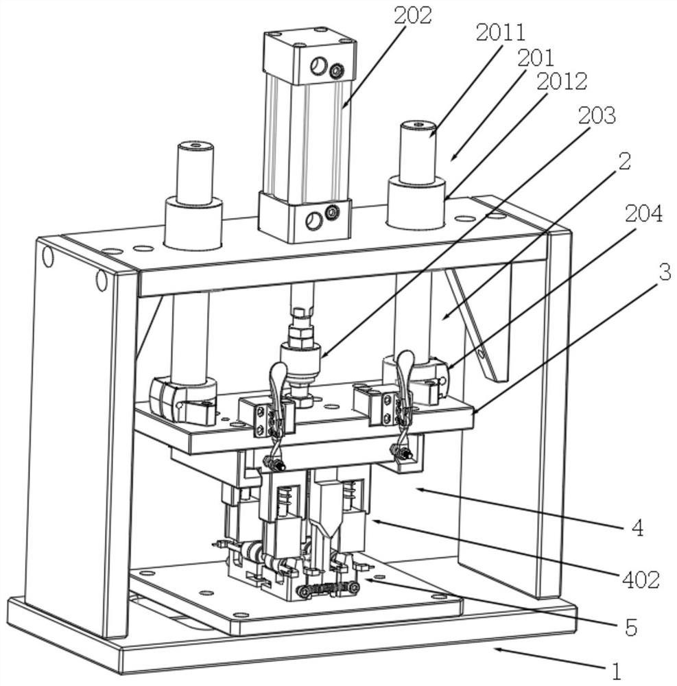
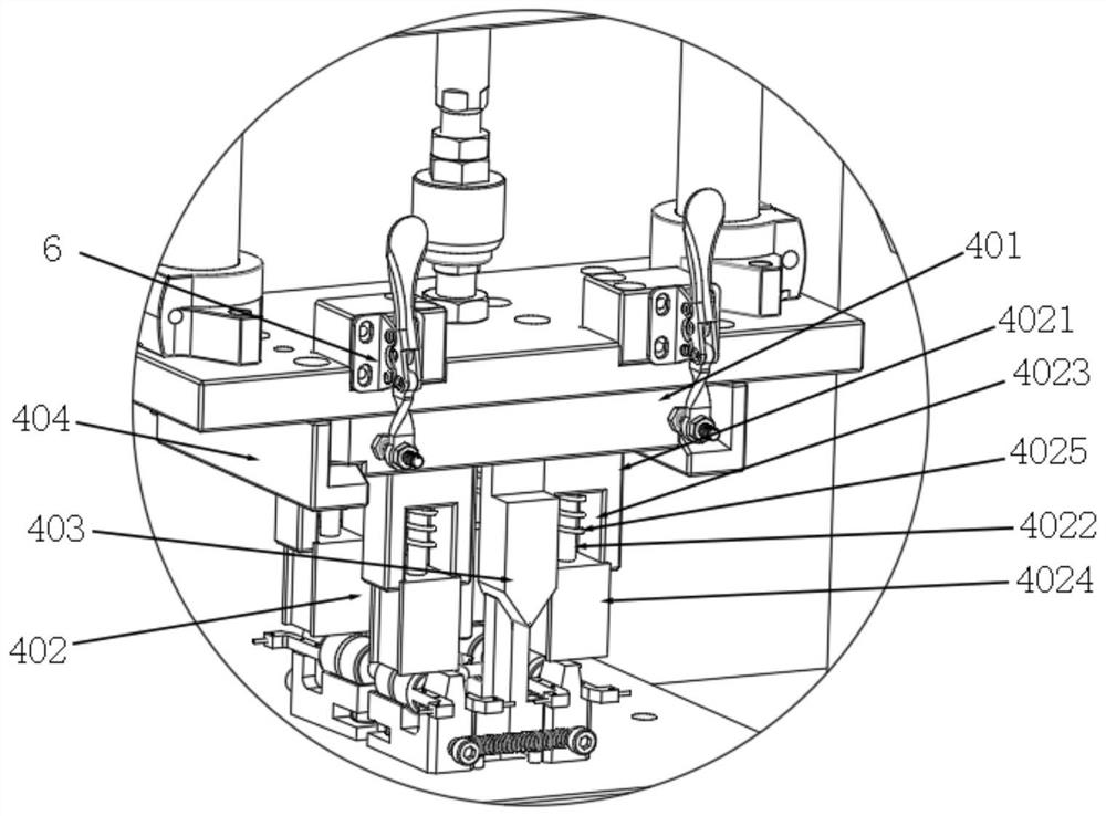
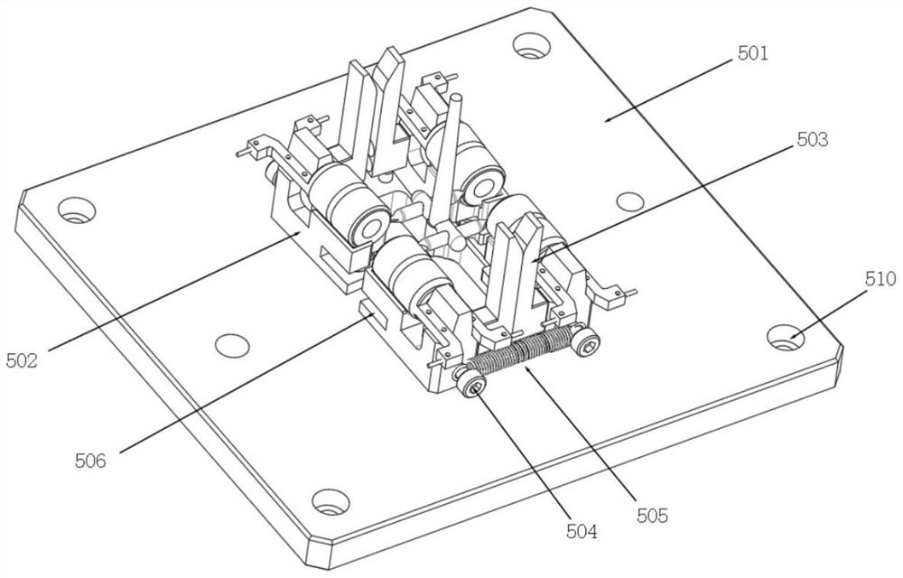
[0028] like Figure 1 to Figure 4 As shown, a punching collector ring nozzle device includes a base 1, a flushing mechanism 2 that moves up and down is installed on the top of the base 1, a fixing plate 3 is matched and connected to the lower end of the flushing mechanism 2, and the lower end of the fixing plate 3 is matched and installed The limit separation mechanism 4, the bottom of the base 1 is provided with a bearing mechanism 5...


PUM


Abstract

The invention discloses a punching collector ring nozzle device, comprising a base, a flushing mechanism that moves up and down is installed on the top of the base, a fixed plate is matched and connected to the lower end of the flushing mechanism, and a limited separation mechanism is matched to the lower end of the fixed plate. The bottom of the base is provided with a bearing mechanism corresponding to the limit separation mechanism. The limit separation mechanism is used to press and separate the workpieces to be processed on the bearing mechanism. In this way of separating the product from the nozzle, there is no punching knife, and there is no problem that the punching knife is too close to the product, which directly avoids damage to the product, and through this method of punching the nozzle, the nozzle of the product is naturally broken, and the entire ring The nozzle material will fall off, and the residual margin is very small, which avoids the increase of secondary processing in the subsequent process.

Description

technical field [0001] The invention relates to the field of punching, in particular to a punching collector ring nozzle device. Background technique [0002] Slip ring is also called conductive ring, slip ring, collector ring, collector ring, etc. It can be used in any electromechanical system that requires continuous rotation while transmitting power and signals from a fixed position to a rotating position. The collector ring products are annular, and the junction between the nozzle material and the collector ring is also annularly joined. When the collector ring product is injection molded, this annular joint method can best reflect that the products are in a saturated state and will not appear. Insufficient injection and other problems, so the joint of this nozzle is used. [0003] However, the disadvantage of this joint method is that the traditional flushing nozzle device is a straight up and straight down punching knife to punch down the joint. This method cannot flu...

Claims


Application Information

Patent Timeline
Patent Type & Authority Patents(China)
IPC IPC(8): B29C45/38B26F1/40B26D7/02
CPCB29C45/382B26F1/40B26D7/02
Inventor 李含强汪善平刘凯李大豹孔庆乐
Owner XUZHOU YUNTAI AUTOMOBILE ELECTRICAL APPLIANCE
Why Eureka
Try Eureka