Laminated concrete member and joint structure and construction method thereof

A technology of concrete and components, applied in building components, building structures, floor slabs, etc., can solve troublesome and time-consuming problems

Active Publication Date: 2022-02-11
浙江恒宸建设集团有限公司
View PDF9 Cites 2 Cited by
  • Summary
  • Abstract
  • Description
  • Claims
  • Application Information

AI Technical Summary

Problems solved by technology

[0004] In the process of implementing the present application, the inventor found that there are at least the following problems in this technology: the number of floors 1 is large, and it takes a lot of time to prepare for concrete pouring, which is troublesome

Method used


Image

  • Laminated concrete member and joint structure and construction method thereof
  • Laminated concrete member and joint structure and construction method thereof
  • Laminated concrete member and joint structure and construction method thereof

Examples


Embodiment Construction

[0044] The following is attached Figure 2-8 The application is described in further detail.

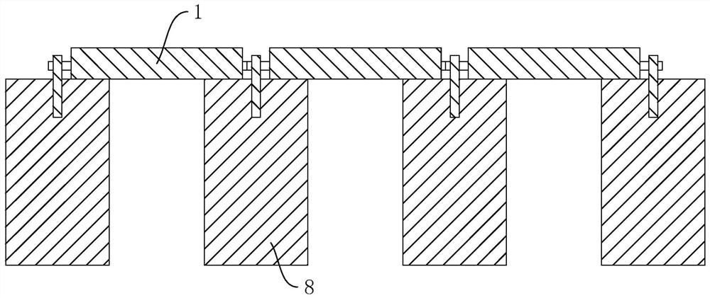
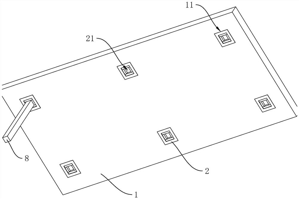
[0045] The embodiment of the present application discloses a composite concrete component. see figure 2 , The superimposed concrete member includes a floor 1, and the bottom of the floor 1 is provided with a plurality of accommodation grooves 11 with openings in a square structure. The floor 1 is provided with an accommodating block 2 , and the accommodating block 2 is clamped and fixed in the accommodating groove 11 . The containing block 2 and the floor 1 can be produced separately. After the production is completed, the containing block 2 is clamped and fixed in the containing groove 11 after smearing cement on the side walls of the containing block 2.

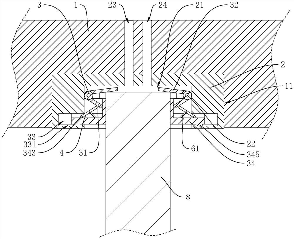
[0046] see image 3 , The middle position of the bottom of the receiving block 2 is provided with an insertion groove 21, the diameter of the insertion groove 21 is larger than the diameter of the column 8, and the column 8 is ...


PUM


Abstract

The invention discloses a laminated concrete member and a node structure and a construction method thereof, and relates to the technical field of building construction. The laminated concrete member comprises a floor slab, a containing groove is formed in the bottom of the floor slab, the floor slab is provided with a containing block, an inserting groove is formed in the bottom of the containing block, and the containing block is provided with a plurality of hinge shafts located in the inserting groove; the peripheral sides of the hinge shafts are sleeved with mounting sleeves, adjusting plates are fixed to the peripheral sides of the mounting sleeves, power plates are arranged on the peripheral sides of the mounting sleeves, mounting grooves are formed in the peripheral groove walls of the inserting grooves, the containing block is provided with closing plates sliding in the mounting grooves, and the adjacent closing plates are in sliding contact with each other. Driving blocks capable of abutting against the side wall of the stand column are arranged on the sides, close to the inserting grooves, of the closing plates, the adjusting plates drive the driving blocks to slide in the direction of the central axis of the inserting grooves when overturning towards the central axis of the inserting grooves, and the floor slab and the containing block are provided with a grouting hole and a grout overflow hole which communicate with each other and communicate with the inserting grooves. The floor slab can be conveniently connected with the stand column.

Description

technical field [0001] The present application relates to the technical field of building construction, in particular to a superimposed concrete component and its node structure and construction method. Background technique [0002] Concrete composite structure is an integral concrete structure formed by post-casting concrete on prefabricated concrete components. It not only has the advantages of cast-in-place integral concrete structure, but also has the advantages of assembled concrete structure. It is a construction speed It is a structural form with fast speed, good integrity and high economic benefits. [0003] see figure 1 , a connection structure of superimposed concrete members, including uprights 8 and floor slabs 1, there are a plurality of floor slabs 1 overlapped at the top of the uprights 8 at even intervals, so that the distance between adjacent floor slabs 1 is the same. Reinforcement bars are reserved around the side of the floor 1, and reinforcement bars a...

Claims


Application Information

Patent Timeline
Patent Type & Authority Applications(China)
IPC IPC(8): E04B5/43E04B5/38
CPCE04B5/43E04B5/38
Inventor 叶土木陆晓文王良宋建新谢丹李云珍姚灿峰张金李欣
Owner 浙江恒宸建设集团有限公司
Why Eureka
Try Eureka