Decorative gridding construction method for heat preservation decorative plate cast-in-place concrete system

A technology of thermal insulation decorative board and construction method, which is applied in the field of wall thermal insulation, and can solve problems such as misalignment and grout leakage

Pending Publication Date: 2022-02-11
山东创伟外墙保温材料集团有限公司
View PDF0 Cites 0 Cited by
  • Summary
  • Abstract
  • Description
  • Claims
  • Application Information

AI Technical Summary

Problems solved by technology

[0003] The present invention proposes a decoration grid construction method when the cast-in-place concrete insulation system of the thermal insulation decorative board is used, and solves the problems of frequent grout leakage and wrong platform when the traditional decoration grid construction method is adopted

Method used


Image

  • Decorative gridding construction method for heat preservation decorative plate cast-in-place concrete system

Examples


Embodiment

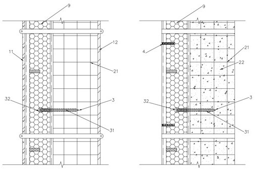
[0019] A construction method for decoration and division of cast-in-place concrete systems with thermal insulation decorative panels, the system includes thermal insulation decorative panels 9, connectors 3, steel bars 21, inner templates 12, outer templates 11, and the connectors 3 include fixing parts 32 and connecting parts 31 , including the following steps:

[0020] (1) Insert the connecting part 32 of the connector 3 into the side of the thermal insulation decorative board 9, the fixed part 32 exposes the thermal insulation decorative board 9 and faces the wall side, and set multiple connectors on the side of the thermal insulation decorative board as required;

[0021] (2) Support the inner formwork 12 and outer formwork 11 of the wall building, and place the thermal insulation decorative board 9 with the connector installed between the inner formwork 12 and the outer formwork 11 of the building, and the fixed part 32 of the connector and the inner formwork 12, The stee...


PUM


Abstract

The invention discloses a decorative gridding construction method for a heat preservation decorative plate cast-in-place concrete system. The system comprises the heat preservation decorative plate, connecting pieces, reinforcing steel bars, an inner formwork and an outer formwork, the connecting piece comprises a fixing part and a connecting part, and the construction method comprises the following procedures that (1) the connecting part of the connecting piece is inserted into the side edge of the heat preservation decorative plate, the fixing part is exposed out of the heat preservation decorative plate and faces one side of a wall, and a plurality of connecting pieces are arranged on the side edge of the heat preservation decorative plate according to needs; (2) the inner formwork and the outer formwork of a wall body building are supported, the heat preservation decorative plate provided with the connecting pieces is arranged between the inner formwork and the outer formwork of the building, the fixing parts of the connecting pieces are connected with steel bars between the inner formwork and the outer formwork of the building in a binding mode, and the decoration face of the heat preservation decorative plate is attached to the inner surface of the outer formwork; (3) after the thermal insulation decorative plate is typeset and fixed, sealing treatment is conducted on a plate seam of the thermal insulation decorative plate; (4) concrete is poured between the non-decorative layer face of the heat preservation decorative plate and the inner formwork of the building, and the heat preservation decorative plate and the steel bars are poured into a whole through the connecting pieces; (5) after the cast-in-place concrete wall body is maintained to reach certain strength, the formworks on the inner side and the outer side of the building are dismantled; and (6) grooves are carved in the thermal insulation decorative plate according to the lattice design.

Description

technical field [0001] The invention relates to the technical field of wall heat preservation, in particular, it relates to a decorative lattice construction method of a cast-in-place concrete system for heat preservation and decorative panels. Background technique [0002] At present, when thermal insulation decorative panels are used in the external thermal insulation project of building exterior walls, it is necessary to produce thermal insulation decorative panels of corresponding sizes according to the layout requirements of the design. After the thermal insulation decorative panels are pasted and fixed to the wall according to the grid spacing, the gaps between the thermal insulation decorative panels are filled and sealed to complete the decorative grid. During the construction of the cast-in-place concrete insulation system, the more the slab gaps, the greater the risk of grout leakage and misalignment between slabs. Therefore, try to use a larger size insulation bo...

Claims


Application Information

Patent Timeline
Patent Type & Authority Applications(China)
IPC IPC(8): E04G21/00E04G11/08E04B2/86E04F13/075E04F13/076
CPCE04G21/00E04G11/08E04B2/86E04F13/072E04F13/0891E04B2002/8682E04F2290/04
Inventor 乔林马强刘亮杨庆伟
Owner 山东创伟外墙保温材料集团有限公司
Why Eureka
Try Eureka