
Full-circle needle beam lining trolley and construction method thereof

A technology of lining trolleys and round needles, which is applied in shaft lining, tunnel lining, earthwork drilling and mining, etc., can solve the problems that the strength of the concrete structure at the bottom is not up to standard, the material distribution mechanism cannot be flexibly adjusted, and the process of opening and closing work windows is cumbersome, etc. The effect of high compaction strength, low labor intensity and fast speed

Pending Publication Date: 2022-02-11
CHENGDU COLITT MACHINERY MFG CO LTD
View PDF0 Cites 0 Cited by
  • Summary
  • Abstract
  • Description
  • Claims
  • Application Information

AI Technical Summary

Problems solved by technology

[0004] However, the existing full-circle needle beam trolley has the following disadvantages: 1. Since the bottom of the tunnel is covered by the bottom formwork, the vibration of the concrete needs to be carried out from the work window opened on the formwork. Due to the limitation of the formwork structure, the number of arrangement of the work windows is limited. The concrete surface that needs to be vibrated cannot be fully taken into account, resulting in the structural strength of the bottom concrete not up to the standard due to insufficient vibration; 2. The process of opening and closing the work window is cumbersome and the distribution mechanism cannot be flexibly adjusted due to the position of the work window when distributing materials, resulting in long construction time; 3. , the large amount of steel used in the bottom formwork will cause a great waste of resources

Method used


Image

  • Full-circle needle beam lining trolley and construction method thereof
  • Full-circle needle beam lining trolley and construction method thereof
  • Full-circle needle beam lining trolley and construction method thereof

Examples


Embodiment Construction

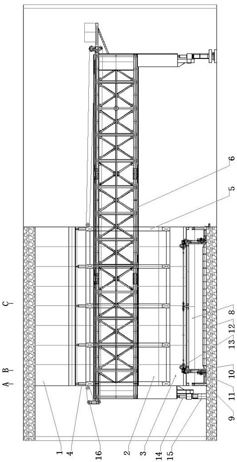
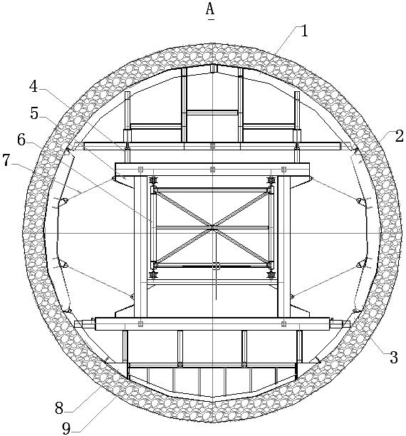
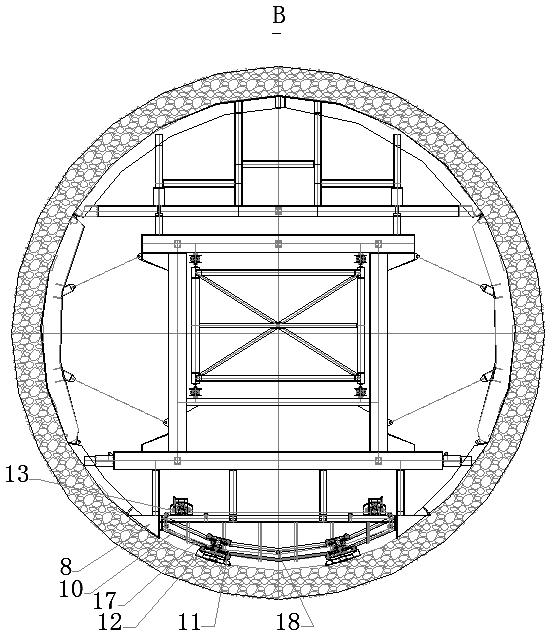
[0042]A full-circle needle beam lining trolley, comprising a top mold 1, a side mold 2, a side mold 3, a top mold oil cylinder 4, a needle beam frame 5, a needle beam 6, a support jack 7, a side beam 8, a longitudinal guide rail 9, a ring Guide rail 10, circular rail trolley 11, sliding template 12, circular rail trolley drive mechanism 13, needle beam oil cylinder 14, needle beam base 15 and needle beam traction mechanism 16. The upper plane of the side beam 8 is rigidly connected with the side mold 3 and the needle beam frame 5, the inner plane is respectively rigidly connected with the longitudinal guide rail 9, the ring guide rail 10, and the needle beam frame 5, and the ring guide rail 10 is slidably connected with the ring rail trolley 11. The rail trolley 11 is rigidly connected to the sliding formwork 12; the ring rail trolley drive mechanism 13 is rigidly connected to the needle beam frame 5, the loop rail trolley drive mechanism 13 is linked with the traction chain 17...


PUM


Abstract

The invention discloses a full-circle needle beam lining trolley and a construction method thereof. The full-circle needle beam lining trolley comprises a top die, side dies, side dies, a needle beam frame and needle beams and is characterized by further comprising side beams, longitudinal guide rails, annular guide rails, an annular rail trolley, a sliding formwork and an annular rail trolley driving mechanism, the needle beam frame is rigidly connected with the side beams, the number of the side beams is two, the upper plane of each side beam is rigidly connected with the side formwork, the longitudinal guide rail and the annular guide rail are located between the two side beams and rigidly connected with the side beams, the annular guide rail is in sliding connection with the annular rail trolley, and the annular rail trolley is rigidly connected with the sliding formwork; and the annular track trolley driving mechanism is rigidly connected to the needle beam frame to drive the annular track trolley to move on the annular guide rail. By the adoption of the full-circle needle beam lining trolley, the bottom of the whole tunnel is in an open state in the lining process, vibration operation is facilitated, vibration exhaust is facilitated, no dead corner exists during vibration, and concrete is high in compactness and strength.

Description

technical field [0001] The invention relates to a construction device in tunnel concrete lining construction, in particular to a full-circle needle beam lining trolley and a construction method thereof, which are used for the construction of tunnel full-section concrete one-time lining. Background technique [0002] The full-circle needle beam trolley is a large-scale formwork equipment used for excavating circular or horseshoe-shaped tunnels for concrete lining construction. [0003] The full-circle needle beam trolley currently in use is mainly composed of: top formwork, side formwork, bottom formwork, needle beam frame, needle beam, needle beam base, support jack, oil cylinder, traction mechanism and other components. The top formwork, side formwork, and bottom formwork can be rotated or stretched through the supporting jack and the oil cylinder base and the needle beam frame when the formwork is erected (removed). The needle beam frame can drive the formwork to slide on ...

Claims


Application Information

Patent Timeline
Patent Type & Authority Applications(China)
IPC IPC(8): E21D11/10
CPCE21D11/102E21D11/105
Inventor 余波
Owner CHENGDU COLITT MACHINERY MFG CO LTD
Learn More