Demand side carbon flow monitoring terminal, monitoring method and system

A monitoring terminal and carbon flow technology, applied in transmission systems, electrical components, etc., can solve the problems of inability to meet indirect carbon emission monitoring, low system response speed, etc., and achieve the effect of improving on-site response efficiency

Pending Publication Date: 2022-02-11
CHINA ELECTRIC POWER RES INST
View PDF2 Cites 4 Cited by
  • Summary
  • Abstract
  • Description
  • Claims
  • Application Information

AI Technical Summary

Problems solved by technology

[0003] The existing carbon flow monitoring terminals are mainly divided into two types: one is to calculate the carbon emissions of energy-consuming equipment or energy-using systems by measuring parameters such as carbon dioxide concentration and gas flow. This method can only be used for direct carbon emissions of energy-consuming units. Monitoring cannot satisfy the monitoring of indirect carbon emissions; the second is to obtain the carbon emission source consumption information of enterprises, calculate carbon emissions according to the corresponding carbon emission accounting method, and upload the server for statistics and analysis. This method is only for energy consumption. Calculation and analysis of carbon emissions of equipment or energy-using systems requires optimization and regulation on the server, resulting in low system response speed

Method used


Image

  • Demand side carbon flow monitoring terminal, monitoring method and system
  • Demand side carbon flow monitoring terminal, monitoring method and system
  • Demand side carbon flow monitoring terminal, monitoring method and system

Examples


Embodiment 1

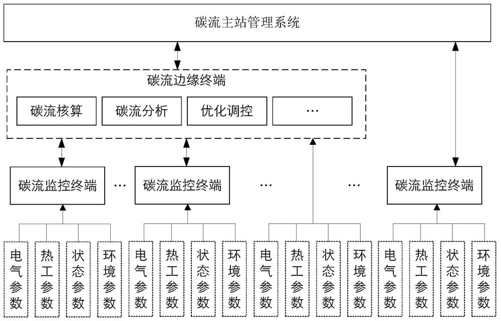
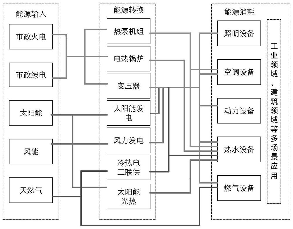
[0068] The invention provides a carbon management system on the demand side, including a carbon flow monitoring terminal, a carbon flow edge terminal and a carbon flow master station arranged on the demand side. The demand side mentioned in the present invention is relative to the supply side, and the supply side refers to the side of centralized energy supply, such as municipal power supply, heat supply, water supply, natural gas supply, etc.; the demand side of the present invention includes the user side The entire business process of energy generation, transmission, transformation and application. There are different systems for different scenarios. For example: air conditioning system, fresh air system, lighting system, power distribution system, elevator system, etc. in public buildings; boiler system, fan system, heating system, energy storage system, etc. in industrial parks. For new energy power generation, large-scale new energy power generation will be distributed ...

Embodiment 2

[0189] Based on the same inventive idea, the present invention also provides a demand-side carbon flow monitoring method, including:

[0190] S1 collects on-site data at the energy consumption end; receives control commands from carbon flow edge terminals;

[0191] S2 brings the field data into a pre-built optimization model to determine a control strategy;

[0192] S3 sends the control strategy and / or the received control command of the carbon flow edge terminal to the energy-consuming terminal;

[0193] Wherein, the optimization model matches control strategies from a plurality of predetermined control strategies based on field data.

[0194] Its specific process is as Figure 4 shown, including:

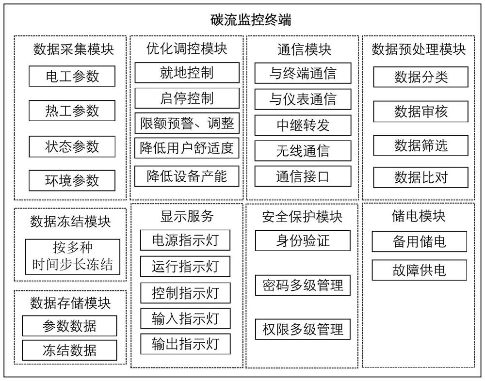
[0195] 1) Collect the electrical parameters, thermal parameters, state parameters and environmental information of the energy consumption site;

[0196] 2) Classify, review, screen and problem data processing for collected data; problem data processing includes: delete duplica...


PUM


Abstract

The invention provides a demand side carbon flow monitoring terminal, monitoring method and system, and the system comprises a data collection module, an optimization regulation and control module and a data communication module, and the data collection module is used for collecting the field data of an energy consumption end; the optimization regulation and control module is used for matching a proper regulation and control strategy from a plurality of regulation and control strategies stored locally by utilizing an optimization model based on field data; the data communication module is used for sending the matched regulation and control strategy to the energy consumption end, sending field data to a carbon flow edge terminal and a carbon flow master station, receiving regulation and control commands of the carbon flow edge terminal and the carbon flow master station and forwarding the regulation and control commands to the energy consumption end; the carbon flow monitoring terminal can directly formulate an on-site regulation and control strategy according to on-site data, and can also carry out regulation and control according to a command of a carbon flow master station or an edge terminal, so that the on-site response efficiency is improved, and meanwhile, the regional regulation and control target is considered, and the carbon emission is reduced to the maximum extent; and meanwhile, the monitoring terminal uploads field data to the edge terminal and the carbon flow master station, so that comprehensive analysis of the energy flow and the carbon flow is realized.

Description

technical field [0001] The invention relates to the field of carbon emission management and monitoring, in particular to a demand-side carbon flow monitoring terminal, monitoring method and system. Background technique [0002] In order to cope with global climate change, achieve the goal of energy conservation and emission reduction, and build a national carbon emission trading market, the regulatory authorities are speeding up the construction of a system to strengthen the supervision of carbon emissions of energy-consuming units; energy-consuming units Actively seek energy-saving and emission-reduction strategies, formulate low-carbon operation measures, and participate in carbon trading market activities; third-party energy-using service units actively understand the carbon emissions of energy-consuming units to provide energy-saving optimization services. In order to ensure the smooth progress of the above work and provide carbon flow data support, it is urgent to estab...

Claims


Application Information

Patent Timeline
Patent Type & Authority Applications(China)
IPC IPC(8): H04L67/125
CPCH04L67/125
Inventor 钟鸣李德智郭毅王松岑霍永锋陈洪银芋耀贤何桂雄张新鹤金璐刘超
Owner CHINA ELECTRIC POWER RES INST
Why Eureka
Try Eureka