Punching forming die

A molding die and workbench technology, which is applied in the field of auto parts processing, can solve problems such as incomplete punching, low work efficiency, and cutting deviation, and achieve the effects of reducing energy consumption losses, improving work efficiency, and improving production safety

Pending Publication Date: 2022-02-15
嘉善悦诚汽车配件有限公司
View PDF0 Cites 0 Cited by
  • Summary
  • Abstract
  • Description
  • Claims
  • Application Information

AI Technical Summary

Problems solved by technology

[0003] There are many types of punching devices for car door parts in the existing market, and the structures are different, but most of them have complex structures, difficult operation by personnel, incomplete punching, and unstable material placement during punching, resulting in cutting deviation and difficult handling Take the cut products, the work efficiency is low

Method used


Image

  • Punching forming die
  • Punching forming die
  • Punching forming die

Examples


Embodiment 1

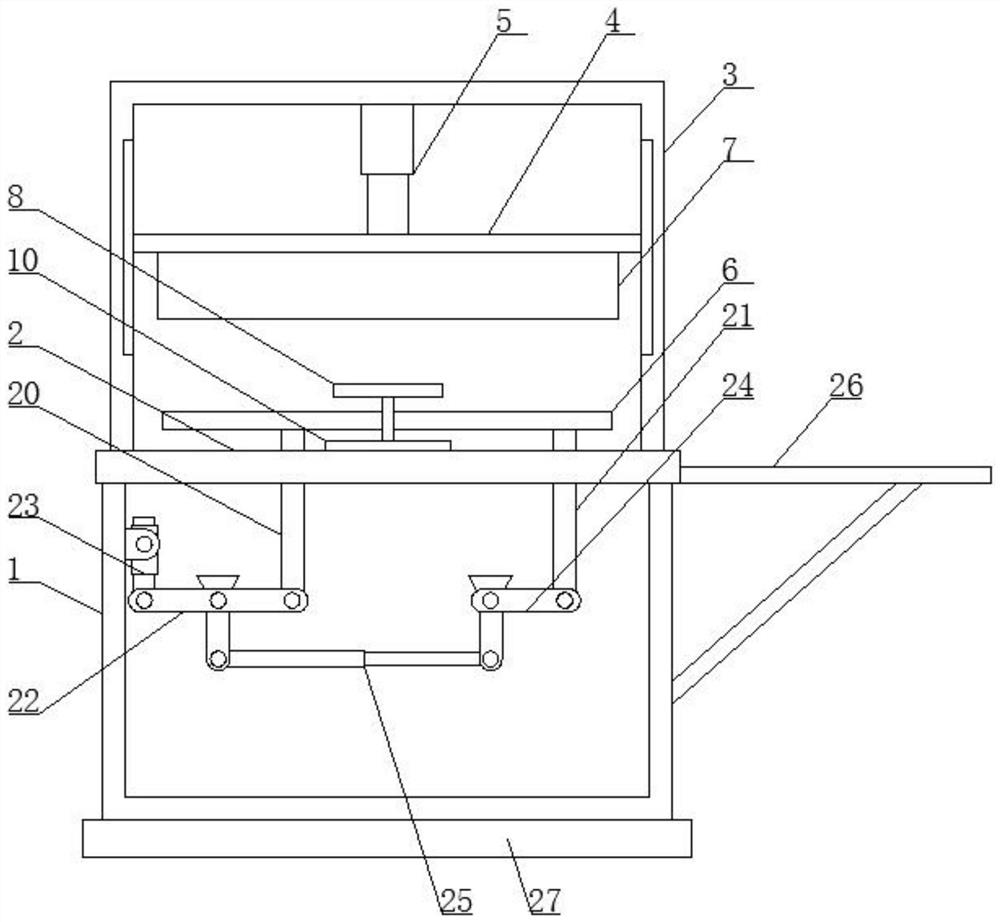
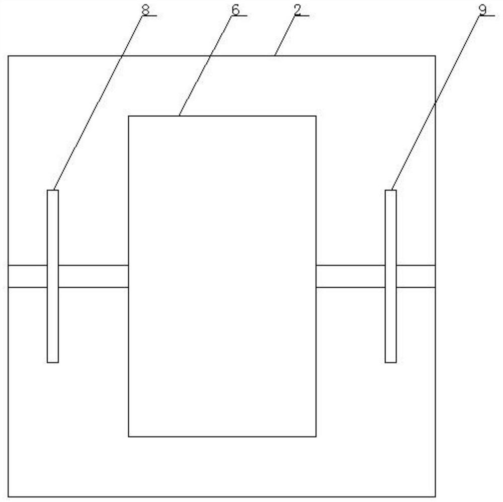
[0025] Such as Figure 1-3 As shown, the punching molding die according to the embodiment of the present invention includes a base 1 and a workbench 2 located at the top of the base 1, the top of the workbench 2 is provided with a housing 3, and the housing 3 It is a cavity structure with side openings, and the housing 3 is provided with a horizontally arranged moving plate 4, and the top end of the moving plate 4 is provided with a telescopic cylinder 5 connected to the housing 3, and the working The top of the platform 2 is provided with a horizontally arranged loading plate 6, the loading plate 6 is connected with the workbench 2 through an adjustment assembly, and the bottom end of the moving plate 4 is provided with a punching block 7, so that The top of the workbench 2 and the both sides of the loading plate 6 are provided with a symmetrically arranged limiting plate one 8 and a limiting plate two 9, and the limiting plate one 8 and the limiting plate two 9 pass through ...

Embodiment 2

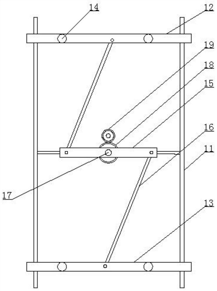
[0028] Such as Figure 1-3 As shown, the movable rod 15 is connected with the horizontal plate 10 through the rotating shaft 17, the rotating shaft 17 is provided with a gear one 18, and one side of the gear one 18 is provided with a transmission gear 19 matched therewith, The shaft center of the transmission gear 19 is connected with the output end of the drive motor located in the horizontal plate 10, and the connecting rod 16 is respectively connected with the movable rod 15, the first slider 12 and the slider through a rotating shaft. Two 13 are connected, and the movable rod 15 is connected with the guide rod 11 through a connecting column.

Embodiment 3

[0030] Such as Figure 1-3 As shown, the adjustment assembly includes a column 1 20 and a column 2 21 symmetrically arranged in the base 1, and the top ends of the column 1 20 and the column 2 21 extend to the top of the workbench 2 and the The loading plate 6 is connected, the bottom end of the column one 20 is provided with a T-shaped bar 22, and the T-shaped bar 22 is connected with the base 1 through a fixed shaft one, and the T-shaped bar 22 One side is provided with the electric telescopic rod 23 that is connected with described base 1, and described T-bar 22 is connected with described electric telescopic rod 23 and described column one 20 respectively by movable shaft one, and described column two 21 The bottom end of the L-shaped rod 24 is provided, and the L-shaped rod 24 is connected with the base 1 through the fixed shaft two, and the bottom end of the L-shaped rod 24 is provided with a A hydraulic telescopic rod 25, the hydraulic telescopic rod 25 is respectively...


PUM


Abstract

The invention discloses a punching forming die, which comprises a base and a workbench located at the top end of the base, wherein a shell is arranged at the top end of the workbench, the shell is of a cavity structure with a side opening, a transversely-arranged moving plate is arranged in the shell, a telescopic air cylinder connected with the shell is arranged at the top end of the moving plate, a transversely-arranged carrying plate is arranged at the top end of the workbench, the carrying plate is connected with the workbench through an adjusting assembly, and a punching block is arranged at the bottom end of the moving plate. The punching forming die has the beneficial effects that through the cooperative design of a limiting assembly, a first limiting plate and a second limiting plate, automobile parts are kept stable during punching, so that the product quality is improved to a certain extent, meanwhile, the working efficiency of workers is improved, meanwhile, the cut products are convenient to take, potential safety hazards possibly caused by the fact that a hand stretches into a machine in the prior art are reduced, and production safety of a workshop is improved.

Description

technical field [0001] The invention relates to the technical field of automobile parts processing, in particular to a punching forming die. Background technique [0002] The door is to provide the passage for the driver and passengers to enter and exit the vehicle, and to isolate the interference with the outside of the vehicle. To a certain extent, it can reduce the impact from the side and protect the occupants. At the same time, the appearance of the car is also related to the structure and shape of the door. A large degree of correlation. [0003] There are many types of punching devices for car door parts in the existing market, and the structures are different, but most of them have complex structures, difficult operation by personnel, incomplete punching, and unstable material placement during punching, resulting in cutting deviation and difficult handling Take the cut product, the work efficiency is low. [0004] Aiming at the problems in the related technologies,...

Claims


Application Information

Patent Timeline
Patent Type & Authority Applications(China)
IPC IPC(8): B21D28/04B21D28/14B21D45/00B21D53/88
CPCB21D28/14B21D53/88B21D28/04B21D45/00
Inventor 杨军孟凡茂王俊山王常宇
Owner 嘉善悦诚汽车配件有限公司
Why Eureka
Try Eureka