Automatic capping mechanism for steel bar thread head

A steel bar and capping technology, which is applied in the field of automatic capping mechanism of steel bar thread head, can solve the problems of high labor cost and low degree of automation, and achieve the effect of improving the overall degree of automation

Pending Publication Date: 2022-02-15
CHENGDU GUTE MACHIENRY WORKS
View PDF0 Cites 0 Cited by
  • Summary
  • Abstract
  • Description
  • Claims
  • Application Information

AI Technical Summary

Problems solved by technology

[0003] The object of the present invention is to provide an automatic capping mechanism for steel bar thread heads to solve the problem of low automaticity and high labor cost in the above-mentioned background technology

Method used


Image

  • Automatic capping mechanism for steel bar thread head
  • Automatic capping mechanism for steel bar thread head
  • Automatic capping mechanism for steel bar thread head

Examples


Embodiment Construction

[0021] The following will clearly and completely describe the technical solutions in the embodiments of the present invention with reference to the accompanying drawings in the embodiments of the present invention. Obviously, the described embodiments are only some, not all, embodiments of the present invention. Based on the embodiments of the present invention, all other embodiments obtained by persons of ordinary skill in the art without making creative efforts belong to the protection scope of the present invention.

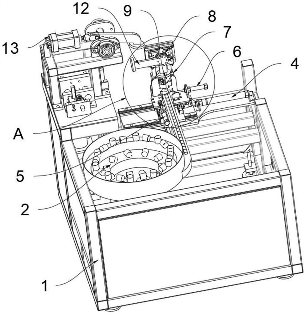
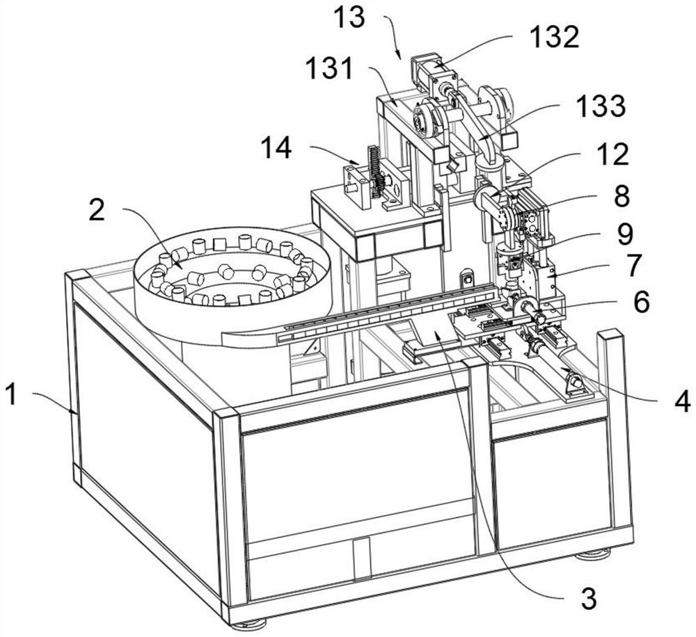
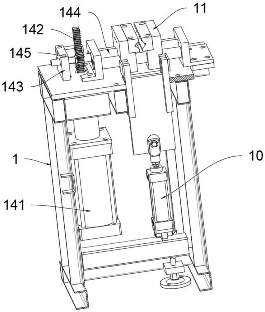
[0022] The present invention provides such Figure 1-5 The shown automatic capping mechanism of a steel bar thread head includes a support frame 1 and a cap sorting machine 2, the cap sorting machine 2 is located at the top of one side of the support frame 1, and a vibrator 3 is installed on the top of one side of the support frame 1, and The vibrator 3 is located at the bottom of the output line of the cap unscrambling machine 2. The cap unscrambling machine ...


PUM


Abstract

The invention discloses an automatic capping mechanism for a steel bar thread head. The automatic capping mechanism comprises a supporting frame and a cap arranging machine, the cap arranging machine is located at the top of one side of the supporting frame, and a vibrator is mounted at the top of one side of the supporting frame and is located at the bottom of an output line of the cap arranging machine; a forward and backward air cylinder and a first sliding plate are mounted at the top of one side of the supporting frame, the output end of the forward and backward air cylinder is connected with the first sliding plate, a left-right moving air cylinder and a second sliding plate are mounted at the top of the first sliding plate, the output end of the left-right moving air cylinder is connected with the second sliding plate, and a cover body positioning air cylinder is mounted at the top of one side of the second sliding plate. A cover grabbing mechanism is fixedly mounted on the outer wall of the top of one side of the first sliding plate, a steel bar positioning air cylinder is mounted at the lower portion of one side of the supporting frame, and the output end of the steel bar positioning air cylinder is connected with a positioning baffle; a steel bar clamp and a power assembly are arranged at the top of one side of the supporting frame, and the output end of the power assembly is connected with the steel bar clamp.

Description

technical field [0001] The invention relates to the technical field of steel bar processing equipment, in particular to an automatic capping mechanism for steel bar thread ends. Background technique [0002] The working process of the traditional sawing and threading production line is sawing, shoveling, threading, and sanding. After sanding, the steel thread head protection cover is manually placed on the thread head, and the cover is manually placed on the thread head. To protect the thread head from being scratched, the simple and simple work of repeatedly putting on the cap will take up two people, which greatly takes up resources, increases labor costs, and reduces the automation of the sawing and threading production line, which does not conform to the automation of modern processing plants. construction requirements. Contents of the invention [0003] The object of the present invention is to provide an automatic capping mechanism for steel bar thread heads to solv...

Claims


Application Information

Patent Timeline
Patent Type & Authority Applications(China)
IPC IPC(8): B23P19/027B23P19/00
CPCB23P19/027B23P19/001
Inventor 黄晓英陈新刚周正述
Owner CHENGDU GUTE MACHIENRY WORKS
Why Eureka
Try Eureka