Welding bogie for rail engineering vehicle

A technology for rail engineering vehicles and bogies, which is applied in the direction of the bogies, devices for lateral relative movement between the chassis and the bogies, railway car body parts, etc. Adapt to the environmental protection requirements of urban rail transit, and cannot meet the problems of loading cargo weight, etc., to achieve the effect of improving lateral stability and operating stability, improving vertical dynamic performance, and improving stability and safety

Pending Publication Date: 2022-02-15
CRRC SHANDONG CO LTD
View PDF12 Cites 0 Cited by
  • Summary
  • Abstract
  • Description
  • Claims
  • Application Information

AI Technical Summary

Problems solved by technology

[0002] At present, the bogies used in subway tunnel engineering vehicles are mostly refitted from passenger cars or ordinary trucks. Since passenger cars are vehicles with small load changes, the bogies are fixed by axle loads, so they cannot meet the requirements of large load changes for engineering vehicles. , and the axle load is small, which cannot meet the requirements of loading goods; although ordinary truck bogies meet the requirements of large load changes and heavy axles, their defects such as low running speed, high noise, and large wear are not suitable for the environmental protection of urban rail transit. Therefore, it is necessary to design a bogie for rail engineering vehicles that meets both the load requirements and the environmental protection requirements of urban rail transit.

Method used


Image

  • Welding bogie for rail engineering vehicle
  • Welding bogie for rail engineering vehicle
  • Welding bogie for rail engineering vehicle

Examples


Embodiment Construction

[0022] The present invention will be specifically described below in conjunction with the accompanying drawings and embodiments.

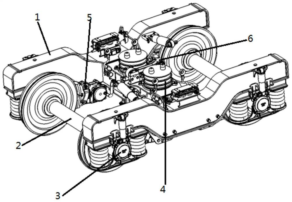
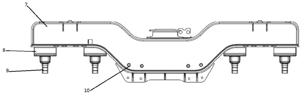
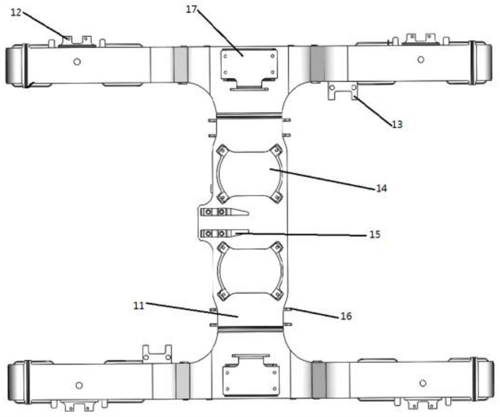
[0023] Such as Figure 1-Figure 7 As shown, the present invention provides a kind of welding bogie for railway engineering vehicles, comprising frame composition 1, wheelset composition 2, axle box suspension device 3, secondary suspension device 4, braking device 5 and traction device 6, described Frame composition 1 is an H-shaped structure formed by welding and splicing side beams 7 and cross beams 11. The side beam 7 is a U-shaped structure, which can lower the center of gravity of the vehicle and improve running stability and safety. Diamond-shaped deformation, strong anti-rhombic ability, meeting the requirements of strength and rigidity; side beam 7 is welded with side bearing seat 17, transverse shock absorber seat 13 and vertical shock absorber seat 12, and cross beam 11 is welded with rubber pile seat 14 , traction seat 15 and anti-jump ...


PUM


Abstract

The invention discloses a welding bogie for rail engineering vehicle; the welding bogie comprises a framework assembly, wheel set assemblies, axle box suspension devices, a secondary suspension device, a brake device and a traction device, the framework assembly is of an H-shaped structure formed by installing and welding side beams and a cross beam, the side beams are of a U-shaped structure, side bearing seats, transverse shock absorber seats and vertical shock absorber seats are welded to the side beams. A rubber pile seat, a traction seat and an anti-jumping seat are welded on the cross beam; the guide frame assembly is arranged at the bottom of the framework assembly; the axle box suspension device is connected to the bottom of the framework assembly; the two ends of each wheel set assembly are supported through the axle box suspension devices, and the framework assemblies are arranged on the two wheel set assemblies. The secondary suspension device comprises a side bearing, a rubber pile, a transverse hydraulic shock absorber and an anti-skipping rope, and the brake device is a brake shoe integrated brake device, is arranged on the inner side of a wheel of the bogie and is mounted on a side beam of the framework assembly; the traction device is arranged on the traction seat; and the cross beam is connected with the vehicle body. The welding bogie is small in dead weight and high in anti-rhombus capacity, and the stability and safety of vehicle operation are improved.

Description

technical field [0001] The invention relates to a rail engineering vehicle bogie, which is suitable for subway tunnel engineering vehicles with a speed level of 120km / h. Background technique [0002] At present, the bogies used in subway tunnel engineering vehicles are mostly refitted from passenger cars or ordinary trucks. Since passenger cars are vehicles with small load changes, the bogies are fixed by axle loads, so they cannot meet the requirements of large load changes for engineering vehicles. , and the axle load is small, which cannot meet the requirements of loading goods; although ordinary truck bogies meet the requirements of large load changes and heavy axles, their defects such as low running speed, high noise, and large wear are not suitable for the environmental protection of urban rail transit. Therefore, it is necessary to design a bogie for rail engineering vehicles that meets both the load requirements and the environmental protection requirements of urban...

Claims


Application Information

Patent Timeline
Patent Type & Authority Applications(China)
IPC IPC(8): B61F5/52B61F5/30B61F5/24
CPCB61F5/52B61F5/308B61F5/24
Inventor 鹿中华柳文豪翟鹏军
Owner CRRC SHANDONG CO LTD
Why Eureka
Try Eureka