Feeding mechanism

The technology of feeding mechanism and hopper is applied in the field of feed or powder feeding, which can solve the problems of increased load, low precision of blanking control, and inability to use the dosing machine, so as to facilitate cleaning and measurement and avoid incomplete cleaning.

Pending Publication Date: 2022-02-15
CHENGDU ZHAOYUAN SCI & TECH CO LTD
View PDF13 Cites 3 Cited by
  • Summary
  • Abstract
  • Description
  • Claims
  • Application Information

AI Technical Summary

Problems solved by technology

[0005] The Chinese patent with authorized notification number CN 206885858 U discloses an anti-arching feed bin. The bottom of the main body of the feed bin is connected with an inverted cone-shaped outlet, and the bottom of the outlet is provided with a valve. The stirring device includes a rotating shaft and a stirring impeller. , the stirring rotor is a spiral curved surface that surrounds the rotating shaft from top to bottom. It can be seen that this scheme uses the rotating shaft in the form of a spiral curved surface to stir the feed in the silo, so as to loosen the feed and avoid arching. However, this scheme As a result, the load on the motor is increased, and the formation of arch can only be partially avoided. It is impossible to control the uniform speed of blanking to achieve accuracy while breaking the arch. The method of setting a valve at the bottom of the discharge port attempts to use the valve to control the blanking while relying on the valve at the same time. The movement of the bottom of the silo vibrates and breaks the arch, thereby controlling the precision of the blanking. However, when the valve is opened, the material falls sharply as an intermittent movement, and it is impossible to continuously and accurately feed the feed in a small amount, and the precision of the blanking cannot be effectively controlled. Therefore, The method of using valves to control the blanking used in this solution also has the problem of low blanking control accuracy, and cannot be used on the dosing machine that needs to be controlled to the milligram level
[0006] The Chinese patent with the authorized notification number CN 205337175 U discloses an anti-arching quantitative feeding device, including a storage bin, a quantitative bin and a sealing mechanism; the bottom of the storage bin is connected to the top of the quantitative bin; the top of the telescopic part of the sealing mechanism Fixed on the top of the storage bin, the bottom of the sealing mechanism is fixed with a lower sealing structure, above the lower sealing structure is fixed an upper sealing structure, the upper sealing structure is located above the quantitative bin, and the lower sealing structure is located below the quantitative bin; the scheme is adopted in the storage bin A sealing structure that moves up and down is set inside, and a quantitative bin is set under the storage bin to realize quantitative feeding. The structure is relatively complicated, and the sealing structure is equivalent to a valve with intermittent movement, and it is impossible to achieve continuous high-precision feeding of powder. (especially powder)

Method used


Image

  • Feeding mechanism
  • Feeding mechanism
  • Feeding mechanism

Examples


Embodiment Construction

[0036]The following will clearly and completely describe the technical solutions in the embodiments of the present invention with reference to the accompanying drawings in the embodiments of the present invention. Obviously, the described embodiments are only some, not all, embodiments of the present invention. Based on the embodiments of the present invention, all other embodiments obtained by persons of ordinary skill in the art without making creative efforts belong to the protection scope of the present invention.

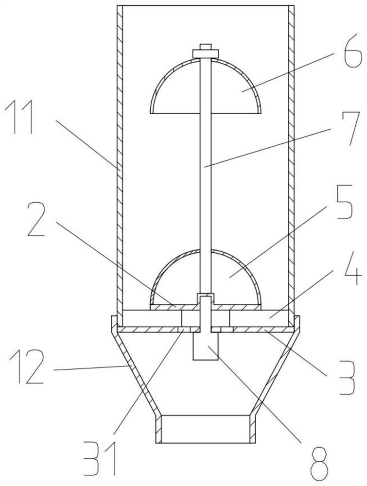
[0037] The purpose of the present invention is to provide a feeding mechanism to solve the existing problems in the prior art. A scraper is used to divide a number of feeding channels between the fixed plate and the baffle plate. The powder can be conveyed to the blanking hole opened on the fixed plate through the feeding channel, and then released from the hopper through the blanking hole. The control of the blanking amount can be realized by controlling the ro...


PUM


Abstract

The invention discloses a feeding mechanism. The feeding mechanism comprises a hopper used for containing powder or granules, and a fixing plate, scrapers and a material blocking plate which are sequentially arranged in the hopper from bottom to top, wherein the fixing plate is used for separating the upper space and the lower space of the hopper, a blanking channel is arranged on the periphery of the material blocking plate, and the part between the fixing plate and the material blocking plate is divided into a plurality of feeding channels by the scrapers; and a blanking hole is formed in an area swept by the scrapers when the scrapers rotate on the fixing plate, and the end part, which is used for receiving materials, of each scraper extends outwards into the area of the blanking channel. According to the invention, the scrapers are used for dividing the part between the fixing plate and the material blocking plate into the plurality of feeding channels, powder falling from the blanking channels can be conveyed into the blanking holes formed in the fixing plate through the feeding channels under the action of the scrapers, and then the powder is thrown out through the blanking holes and the hopper, so that the blanking amount can be controlled by controlling the rotation of the scrapers, and then the blanking precision is accurately controlled.

Description

technical field [0001] The invention relates to the technical field of feed or medicinal powder delivery, in particular to a feeding mechanism. Background technique [0002] During the use of the electric feeding hopper, due to the characteristics of the powdery or granular materials in it, during the process of discharging at the bottom, an arch area will be formed in the hopper. The formation of the arch area is due to the adhesion of the powder to form a transverse arch. The powder in the lower part may form a "bridge arch" cavity. After the feed or powder medicine below is thrown out one after another, the powder in the upper part of the hopper may also form a "horizontal arch" due to mutual static electricity and friction. " area, the cavities in these two areas will destroy the continuous downward flow of powder and reduce the feeding accuracy. If the feed or medicine powder stored in the hopper needs to be stored for a long time or the environment is relatively humid...

Claims


Application Information

Patent Timeline
Patent Type & Authority Applications(China)
IPC IPC(8): B65G65/48B65G69/00B65D90/00B65D88/68A01K5/00
CPCA01K5/00B65G65/4818B65G65/4872B65G69/00B65D88/68B65D90/00
Inventor 夏天
Owner CHENGDU ZHAOYUAN SCI & TECH CO LTD
Why Eureka
Try Eureka