
Self-dewatering type winding device for textile processing

A winding device and dehydration-type technology, which is applied to heating devices, coiling strips, transportation and packaging, etc., can solve the problems of time-consuming, electric energy, cloth quality degradation, cloth marks, etc., and achieve the effect of improving processing quality

Inactive Publication Date: 2022-02-15
邓代红
View PDF0 Cites 0 Cited by
  • Summary
  • Abstract
  • Description
  • Claims
  • Application Information

AI Technical Summary

Problems solved by technology

[0003] Among them, when the dyed textile cloth is rolled, because the cloth is very wet after being soaked in the dye solution, the cloth has a certain viscosity, and a large number of wrinkles often appear when it is rolled again, so that the cloth will be rolled together for a long time. Obvious print marks appear, resulting in a decline in the quality of the cloth; if it is to be dried and dehydrated by special drying equipment (such as a dryer, etc.) before winding, it will not only consume man-hours and electricity, but also need to transport the cloth to the drying equipment Drying in the oven will inevitably cause wrinkles in the fabric

Method used

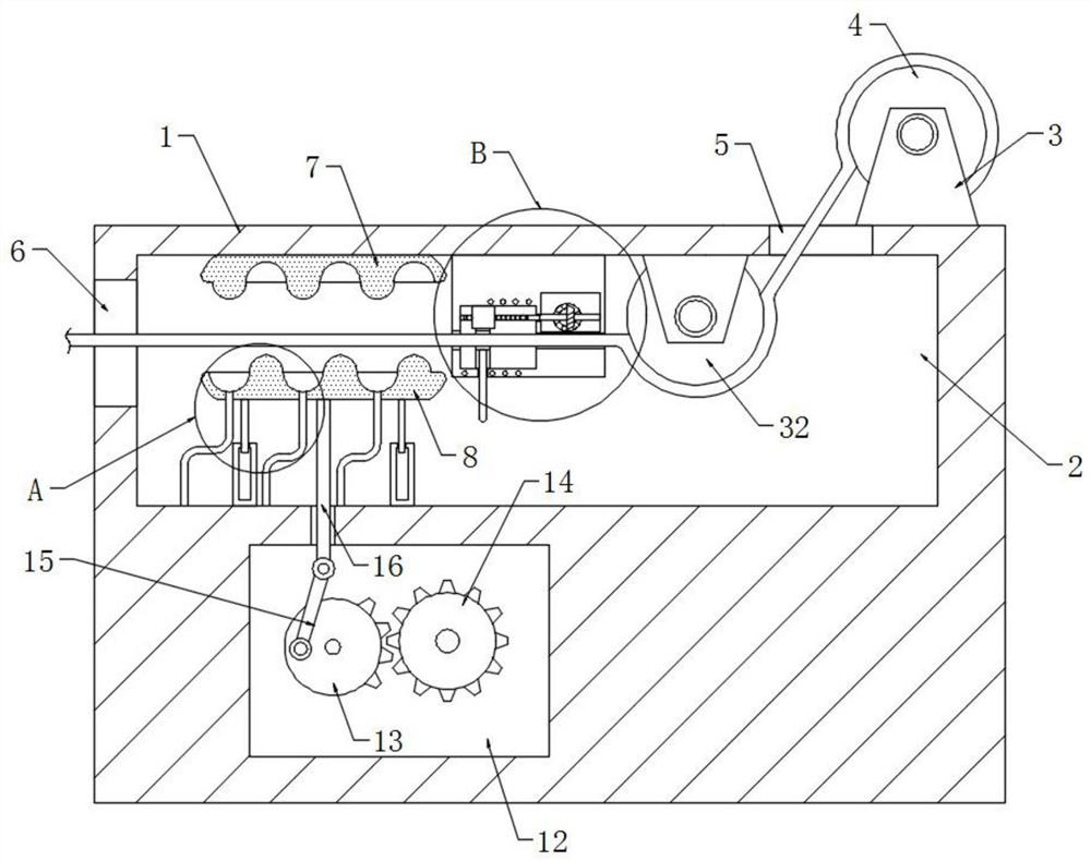

Image

  • Self-dewatering type winding device for textile processing
  • Self-dewatering type winding device for textile processing
  • Self-dewatering type winding device for textile processing

Examples


Embodiment Construction

[0024] The following will clearly and completely describe the technical solutions in the embodiments of the present invention with reference to the accompanying drawings in the embodiments of the present invention. Obviously, the described embodiments are only some, not all, embodiments of the present invention.

[0025] In describing the present invention, it should be understood that the terms "upper", "lower", "front", "rear", "left", "right", "top", "bottom", "inner", " The orientation or positional relationship indicated by "outside", etc. is based on the orientation or positional relationship shown in the drawings, and is only for the convenience of describing the present invention and simplifying the description, rather than indicating or implying that the referred device or element must have a specific orientation, so as to Specific orientation configurations and operations, therefore, are not to be construed as limitations on the invention.

[0026] refer to Figure ...


PUM


Abstract

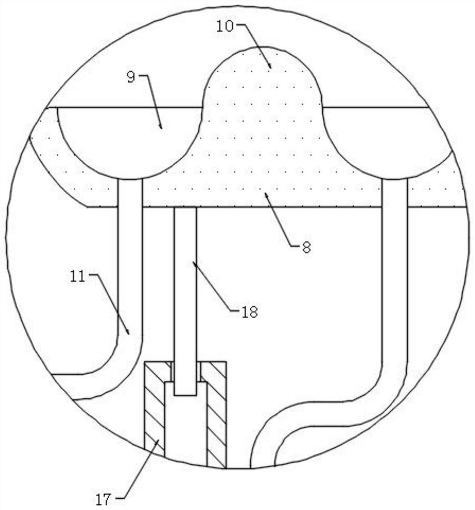
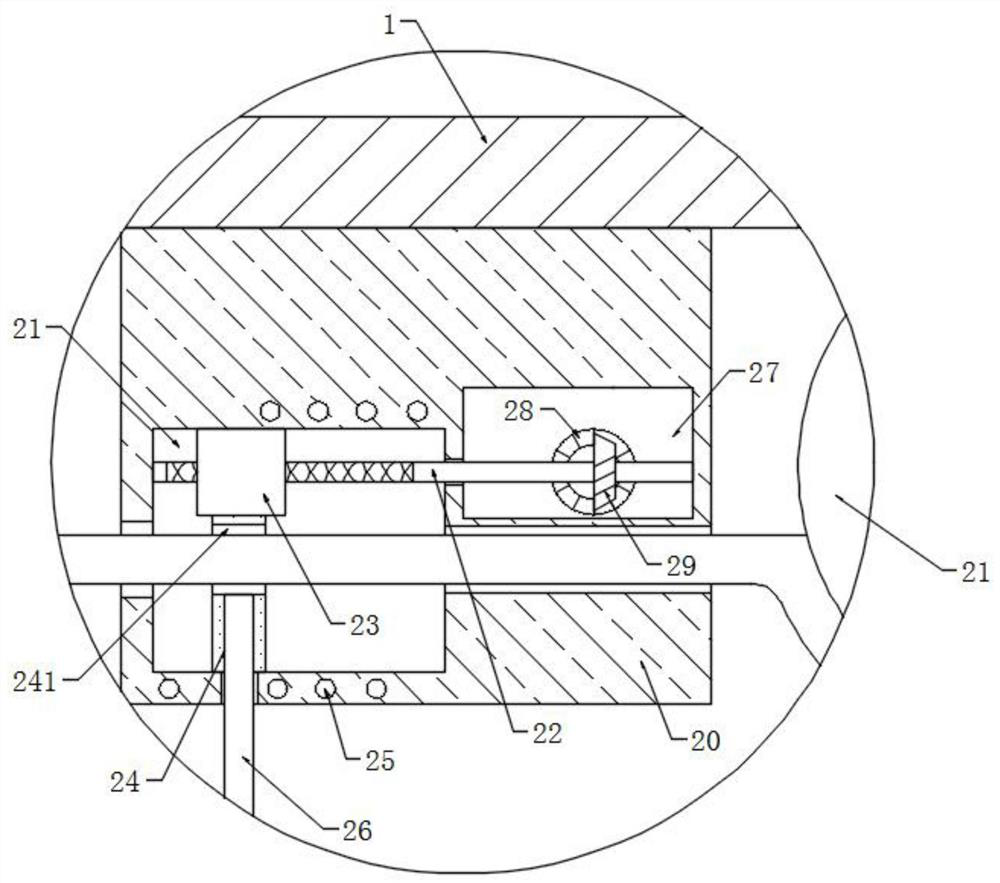
The invention discloses a self-dewatering type winding device for textile processing. The device comprises a winding table, wherein two fixing seats are fixedly connected to the winding table, a winding roller is rotationally connected between the two fixing seats, a dewatering groove is formed in the side wall of the winding table, an upper pressing plate is fixedly connected to the inner top of the dewatering groove, a lower pressing plate is slidably connected into the dewatering groove, semi-cylindrical grooves are formed in the opposite side walls of the lower pressing plate of the upper pressing plate, liquid discharging pipes are arranged at the bottoms in the semi-cylindrical grooves, semi-cylindrical pressing rollers are fixedly connected to the opposite side walls of the lower pressing plate of the upper pressing plate, and a square groove is formed in the side wall of the winding table. According to the invention, a driving device continuously pushes a lower pressing plate to eject upwards, so that semi-cylindrical grooves are in extrusion contact with semi-cylindrical pressing rollers so as to extrude out water on cloth; and by arranging a flattening plate and pushing the flattening plate to move back and forth, the conveyed cloth can be flattened, so that wrinkles are prevented so as to improve the processing quality of the cloth.

Description

technical field [0001] The invention relates to the technical field related to textile processing, in particular to a self-dehydrating winding device for textile processing. Background technique [0002] In the textile processing process, a winding device is often used to wind up the textile cloth after spinning, dyeing and other processes on the winding roller to facilitate transportation or subsequent processing. [0003] Among them, when the dyed textile cloth is rolled, because the cloth is very wet after being soaked in the dye solution, the cloth has a certain viscosity, and a large number of wrinkles often appear when it is rolled again, so that the cloth will be rolled together for a long time. Obvious print marks appear, resulting in a decline in the quality of the cloth; if it is to be dried and dehydrated by special drying equipment (such as a dryer, etc.) before winding, it will not only consume man-hours and electricity, but also need to transport the cloth to t...

Claims


Application Information

Patent Timeline
IPC IPC(8): B65H18/10B65H23/34B65H23/038F26B13/10F26B21/00F26B23/06
CPCB65H18/10B65H23/34B65H23/038F26B13/10F26B21/004F26B23/06B65H2701/174
Inventor 邓代红
Owner 邓代红
Learn More