Lifting appliance applied to vehicle machining

A spreader and vehicle technology, applied in the direction of load block, clockwork mechanism, load suspension components, etc., can solve the problems of inconvenient use, lack of transportation effect, poor transportation efficiency, etc., and achieve the effect of improving stability

Pending Publication Date: 2022-02-15
HEFEI CHANGQING MACHINERY
View PDF0 Cites 0 Cited by
  • Summary
  • Abstract
  • Description
  • Claims
  • Application Information

AI Technical Summary

Problems solved by technology

[0004] The purpose of the present invention is to solve the problems that the existing spreader only has the lifting function and lacks the transportation effect, which makes it inconvenient to use, and the transportation stability is poor, and the transportation efficiency is poor. Lifting spreader

Method used


Image

  • Lifting appliance applied to vehicle machining
  • Lifting appliance applied to vehicle machining
  • Lifting appliance applied to vehicle machining

Examples


Embodiment 1

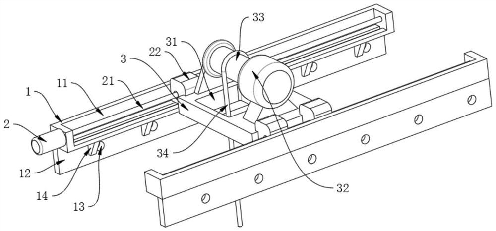
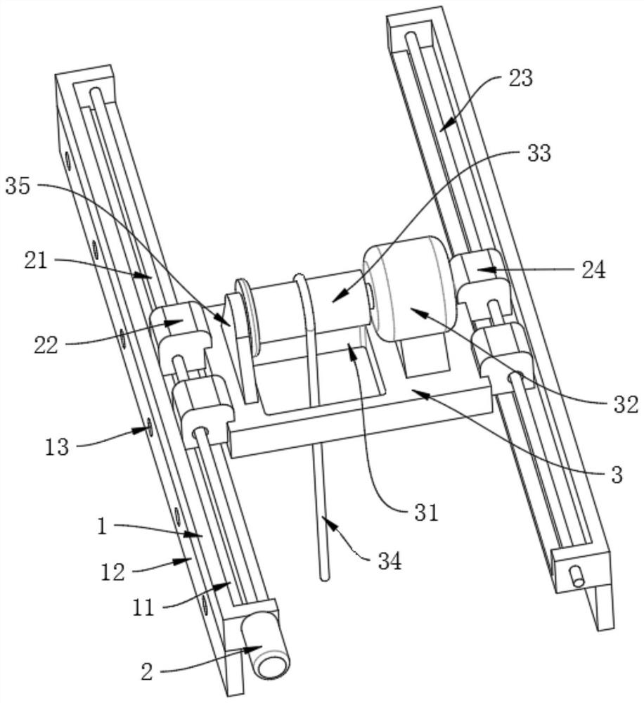
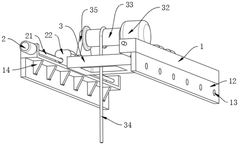
[0021] Example 1, such as Figure 1-3 As shown, the present invention provides a hoisting spreader applied to vehicle processing, comprising two symmetrically arranged carriages, the carriages comprising a sliding seat 1, the upper surface of the sliding seat 1 is provided with a chute 11, and the lower surface of the sliding seat 1 is The surface is fixedly connected with a fixed plate 12, the outer surface of the fixed plate 12 is uniformly provided with a plurality of connecting holes 13, the inner surface of the fixed plate 12 is fixedly connected with a reinforcing rib 14, and the reinforcing rib 14 is fixedly connected with the bottom of the sliding seat 1;

[0022] Wherein the outer surface of the carriage is fixedly connected with the first motor 2, the driving end of the first motor 2 is fixedly connected with the threaded rod 21, the outer surface of the threaded rod 21 is threaded with two first sliding blocks 22, and the inner surface of the other carriage is fixedl...

Embodiment 2

[0024] Example 2, such as Figure 1-3 As shown, the threaded rod 21 is located inside the chute 11, and the end surface of the threaded rod 21 is rotationally connected with the inner surface of the sliding seat 1, the outer surfaces of the two first sliding blocks 22 are slidably connected with the chute 11, and the outer surfaces of the two second sliding blocks 24 are The surface is slidably connected with the chute 11, the outer surfaces of the two first sliding blocks 22 and the two second sliding blocks 24 are fixedly connected with a fixed seat 3, the upper surface of the fixed seat 3 is provided with a through hole 31, and the upper surface of the fixed seat 3 is fixedly connected There is a second motor 32, the driving end of the second motor 32 is fixedly connected with a rotating cylinder 33, the end surface of the rotating cylinder 33 is rotatably connected with a rotating seat 35, the lower surface of the rotating seat 35 is fixedly connected with the upper surface...


PUM


Abstract

The invention provides a lifting appliance applied to vehicle machining, and relates to the technical field of vehicle machining. The lifting appliance comprises two symmetrically arranged sliding frames, each sliding frame comprises a sliding seat, and the upper surface of each sliding seat is provided with a sliding groove; the lower surface of each sliding seat is fixedly connected with a fixing plate, the outer surface of each fixing plate is uniformly provided with a plurality of connecting holes, and reinforcing ribs are fixedly connected to the inner surface of the fixing plate and are fixedly connected with the bottom of the sliding seat, wherein a first motor is fixedly connected to the outer surface of the sliding frame. The two sliding frames are arranged, the sliding grooves are formed in the sliding seats, then the first motor is started to drive the threaded rods to rotate, and therefore the first sliding blocks are driven to slide along the sliding grooves and cooperate with the second sliding blocks to slide along the sliding rods, so that the fixing seats are driven to slide, and the purpose of transportation is achieved; and a second motor is cooperatively started to drive a rotating cylinder to rotate, so that a bottom pull rope is driven to ascend and descend, and the lifting work is completed.

Description

technical field [0001] The invention relates to the technical field of vehicle processing, in particular to a hoisting spreader applied to vehicle processing. Background technique [0002] In the automobile manufacturing industry, for example, auto parts such as bumpers and rear floor beams are assembled sequentially during the assembly process, and the vehicles are transported to the corresponding assembly locations. [0003] The existing spreader only has the lifting function and lacks the transportation effect, which makes it inconvenient to use, and the transportation stability is poor, and the transportation efficiency is poor. Therefore, we propose that a lifting spreader for vehicle processing is needed. . Contents of the invention [0004] The purpose of the present invention is to solve the problems that the existing spreader only has the lifting function and lacks the transportation effect, which makes it inconvenient to use, and the transportation stability is ...

Claims


Application Information

Patent Timeline
Patent Type & Authority Applications(China)
IPC IPC(8): B66C11/00B66C9/00B66D1/12
CPCB66C11/00B66C9/00B66D1/12
Inventor 吴应举
Owner HEFEI CHANGQING MACHINERY
Why Eureka
Try Eureka