Tube well tube lifting device

A lifting device and pipe technology, applied in the direction of lifting device, hoisting device, etc., can solve the problems of complicated lifting operation of tube well, easy deformation of pipes, low efficiency, etc., and achieve the effect of small occupied space, simple structure and high efficiency

Pending Publication Date: 2022-02-15
WUHAN YIYE CONSTR ENG +1
View PDF6 Cites 0 Cited by
  • Summary
  • Abstract
  • Description
  • Claims
  • Application Information

AI Technical Summary

Problems solved by technology

[0002] The pipe well needs to be lifted and lowered during the dewatering construction of the tube well. The current tube well lifting operation is complicated, dangerous, high in cost and low in efficiency, and the pipe is easily deformed during the lifting process.

Method used


Image

  • Tube well tube lifting device
  • Tube well tube lifting device

Examples


Embodiment Construction

[0015] The present invention will be further described below in conjunction with the accompanying drawings and embodiments.

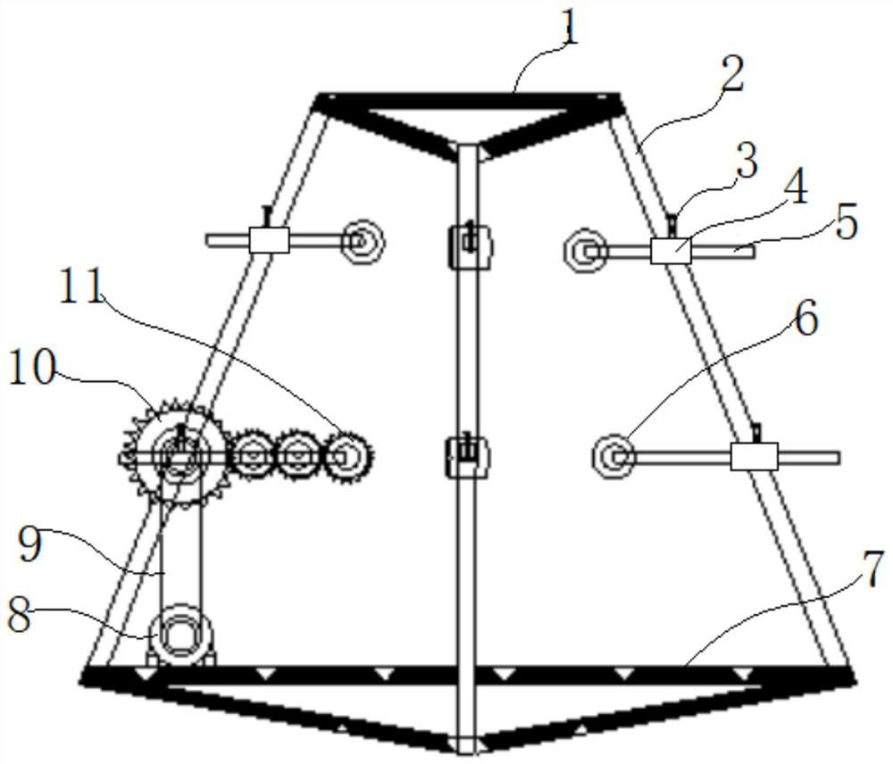
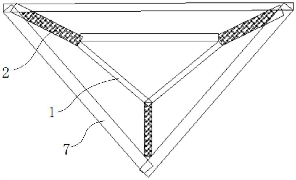
[0016] Such as figure 1 with figure 2 As shown, a pipe well pipe lifting device includes a frame body, and the frame body includes a bottom triangular frame 7 as a base, a top triangular frame 1 directly above the bottom triangular frame 7, and each of the bottom triangular frame 7 and the top triangular frame 1 For the support rods 2 connected one by one to the corresponding angles, the top of one support rod 2 is provided with a limit rod 5, the bottom is provided with a driving roller 11, and the upper and lower parts of the other two support rods 2 are respectively provided with a limit rod 5, and the limit The rod 5 can be horizontally moved and locked, and the inward end is provided with a limit wheel 6, and the bottom triangle frame 7 is provided with a motor 8, and the motor 8 drives the drive roller 11 forward and reverse through the transmis...


PUM


Abstract

The invention discloses a tube well tube lifting device which comprises a frame body. The frame body comprises a bottom triangular frame, a top triangular frame and supporting rods, the upper portion of one supporting rod is provided with a limiting rod, the lower portion of one supporting rod is provided with a driving roller, and the upper portions and the lower portions of the other two supporting rods are each provided with a limiting rod. The limiting rods can be horizontally moved and locked, limiting wheels are arranged at the inward ends of the limiting rods, a motor is arranged on the bottom triangular frame, and the motor drives a driving roller to rotate forwards and backwards through a transmission mechanism. During work, the bottom triangular frame is arranged at a wellhead of a tube well, a tube penetrates through the top triangular frame and the bottom triangular frame, the three limiting rods at the upper layer limit the upper point of the tube from three directions, the two limiting rods at the lower layer and the driving roller limit the lower point of the tube from three directions, the limiting wheel is in rolling fit with the outer wall of the tube, and the motor drives the tube to ascend and descend through the driving roller. The device avoids the deformation of the tube, is simple and safe to operate and is high in efficiency, can ensure the coherence of tube operation, and is convenient to manufacture, mount and transfer.

Description

technical field [0001] The invention belongs to the field of tube well dewatering construction, and in particular relates to a tube well pipe lifting device. Background technique [0002] The pipe well needs to be lifted and lowered during the dewatering construction of the tube well. The current tube well lifting operation is complicated, dangerous, high in cost and low in efficiency, and the pipe is easily deformed during the lifting process. Contents of the invention [0003] The object of the present invention is to provide a pipe well pipe lifting device, which avoids pipe deformation, is simple, safe and efficient to operate, can ensure the continuity of pipe operation, and is convenient for manufacture, installation and transfer. [0004] The technical scheme adopted in the present invention is: [0005] A tube well pipe material lifting device, including a frame body, the frame body includes a bottom triangular frame as a base, a top triangular frame directly abov...

Claims


Application Information

Patent Timeline
Patent Type & Authority Applications(China)
IPC IPC(8): B66F19/00
CPCB66F19/00
Inventor 赵映周亭周全
Owner WUHAN YIYE CONSTR ENG
Why Eureka
Try Eureka