Automatic test device and test method for multi-beam assembly

An automatic test device and automatic test technology are applied in the direction of measuring devices, measuring electricity, and measuring electrical variables. small effect

Active Publication Date: 2022-02-15
SOUTHWEST CHINA RES INST OF ELECTRONICS EQUIP
View PDF10 Cites 0 Cited by
  • Summary
  • Abstract
  • Description
  • Claims
  • Application Information

AI Technical Summary

Problems solved by technology

The entire system is bulky, and for components that require phase consistency, it is difficult to calibrate the phase between multiple RF transfer cables. In addition, the switch matrix is ​​expensive, and such a system is difficult to popularize in actual use.

Method used


Image

  • Automatic test device and test method for multi-beam assembly
  • Automatic test device and test method for multi-beam assembly
  • Automatic test device and test method for multi-beam assembly

Examples


Embodiment 1

[0034] In the traditional multi-channel microwave component test, RF input and output modules are installed at both ends of the component under test. After the input and output modules, a switch matrix must be relied on to realize one-button automatic testing. This test method needs to use RF cables to transfer each channel of the RF input and output module to the switch matrix, and then connect the switch matrix to instruments such as Yanet. The entire system is bulky, and for components that require phase consistency, it is difficult to calibrate the phase between multiple RF transfer cables. In addition, the switch matrix is ​​expensive, and such a system is difficult to popularize in actual use.

[0035] In order to solve the above technical problems, the following various embodiments of the multi-channel microwave component testing device are proposed.

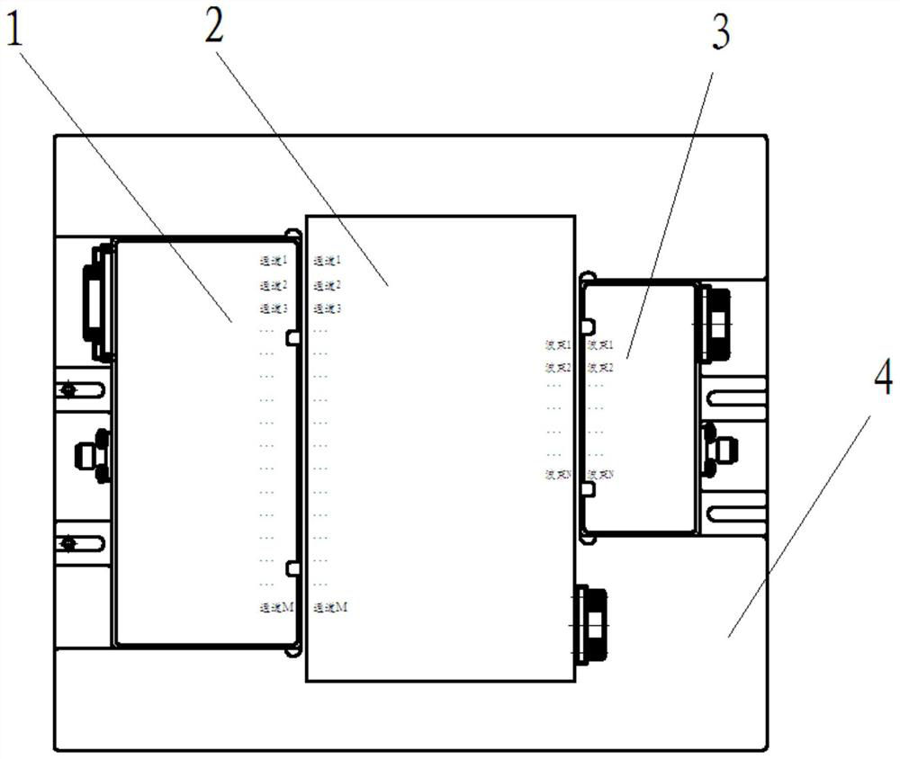
[0036] refer to figure 1 ,Such as figure 1 Shown is a schematic structural diagram of the multi-beam component automa...

Embodiment 2

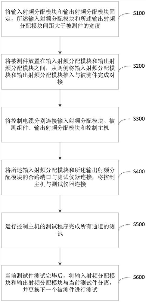
[0049] Based on the automatic test device for multi-beam components provided in the foregoing embodiments, this embodiment provides a method for automatically testing multi-beam components using the automatic test device. refer to image 3 ,Such as image 3 Shown is a schematic flowchart of a method for automatically testing a multi-beam component provided in this embodiment. The method specifically includes the following steps:

[0050] Step S100: Fix the input radio frequency distribution module and the output radio frequency distribution module, the distance between the input radio frequency distribution module and the output radio frequency distribution module is greater than the width of the component under test.

[0051] Specifically, the RF distribution module is first fixed on the support base with screws, only 1 or 2 screws are needed for installation, and after installation, there is no need to disassemble it during the entire subsequent testing process.

[0052] ...


PUM


Abstract

The invention discloses an automatic test device and a test method for a multi-beam assembly. The device comprises an input radio frequency distribution module and an output radio frequency distribution module. The input radio frequency distribution module and the output radio frequency distribution module are provided with a radio frequency connector connected with a test instrument and a control interface connected with a control host outside, and a radio frequency signal distribution circuit for dividing a radio frequency signal into multiple parts is arranged in the input radio frequency distribution module; the output radio frequency distribution module comprises a radio frequency signal synthesis circuit for combining multiple radio frequency signals into one inside, and each branch of the radio frequency signal distribution circuit and the radio frequency signal synthesis circuit is provided with a control switch. The automatic test device for the multi-beam assembly, provided by the invention, is low in cost, small in size and easy to use, can realize synchronous control of the test instrument, the radio frequency distribution module and the tested assembly, and can complete performance tests of all channels through one-time installation and one key.

Description

technical field [0001] The invention belongs to the technical field of microwave component testing, and in particular relates to a multi-beam component automatic testing device and testing method. Background technique [0002] The multi-beam component is the core unit of the multi-beam phased array system. It has the characteristics of multiple inputs and multiple outputs. The combination of each input and output is an independent channel and needs to be tested separately. Therefore, a single component contains a large number of channels. , usually a single component contains dozens or even hundreds of channels. Manual operation switching channel test is not only inefficient but also error-prone. It is an inevitable choice to improve test efficiency to realize one-button automatic test through auxiliary test modules. [0003] For example, the Chinese invention patent with the publication number CN107422199A discloses a multi-channel microwave component testing system. The i...

Claims


Application Information

Patent Timeline
Patent Type & Authority Applications(China)
IPC IPC(8): G01R31/00
CPCG01R31/00Y02D30/70
Inventor 曾超周丽揭海丁义超杜立新
Owner SOUTHWEST CHINA RES INST OF ELECTRONICS EQUIP
Why Eureka
Try Eureka