Goods shelf pipe automatic clamping fixed-distance slitting device
A kind of pipe material and automatic technology, which is applied in the direction of pipe shearing device, shearing device, and the accessory device of shearing machine, etc., can solve the problems of large pipe vibration, long working cycle, low efficiency, etc., achieve fast working cycle, improve work efficiency, high efficiency effect
- Summary
- Abstract
- Description
- Claims
- Application Information
AI Technical Summary
Problems solved by technology
Method used
Image
Examples
Embodiment 1
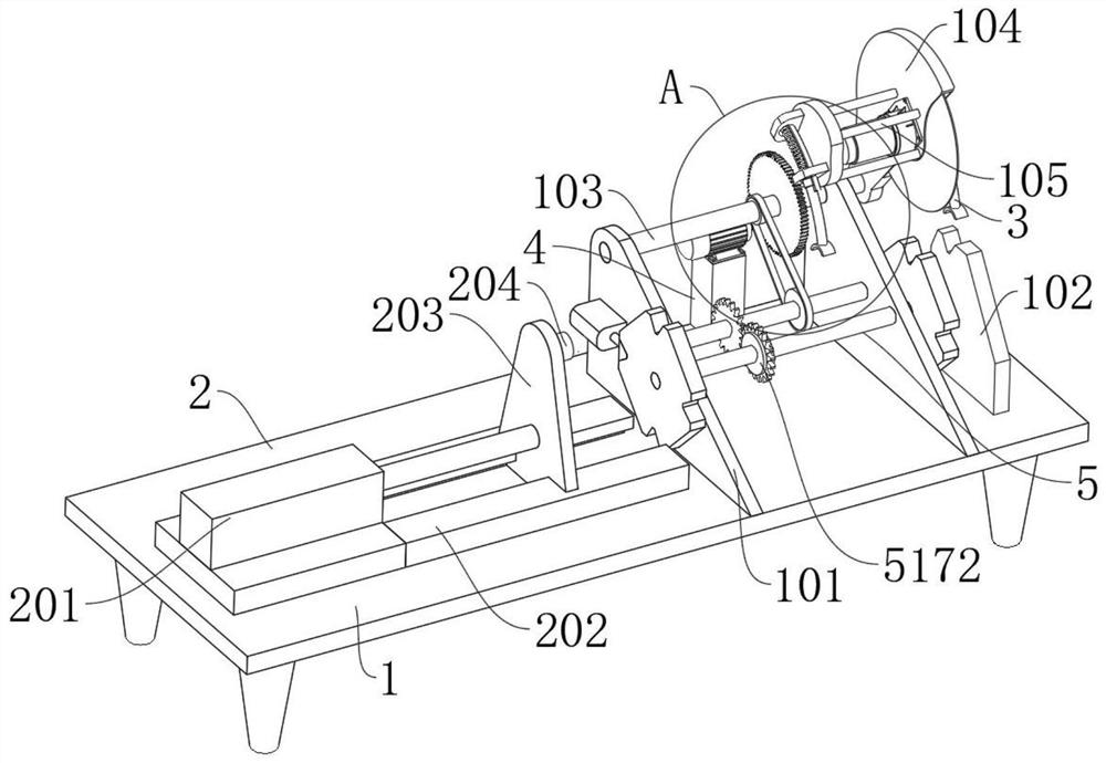
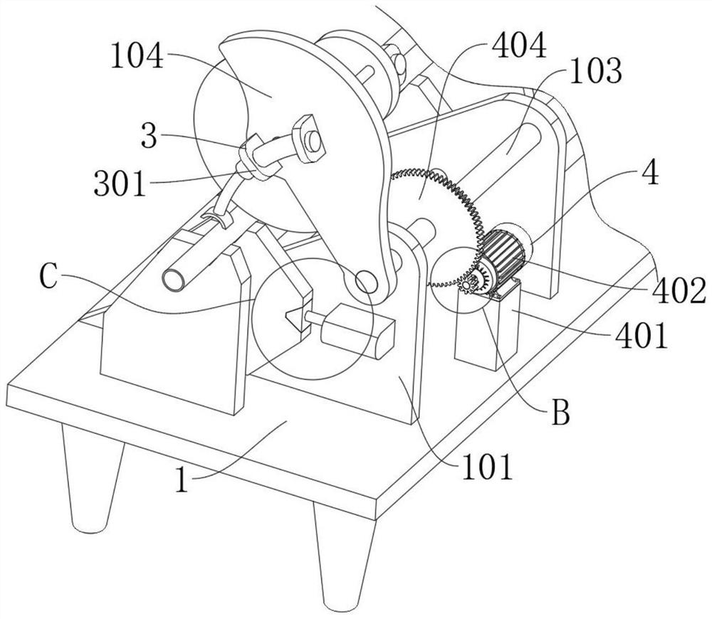
[0030] see Figure 1-Figure 8 , the present invention provides a technical solution: an automatic clamping and cutting device for shelf pipes at a fixed distance, including a workbench 1 on which two support plates 101 are symmetrically fixed, and the two support plates 101 are one A support block 102 fixedly connected to the workbench 1 is provided on one side, and a distance device 2 is installed on the other side of the two support plates 101. A first transmission shaft 103 is rotatably connected between the two support plates 101. The shaft 103 rotates through the support plate 101 and is fixed with a cutting machine 104 near the end of the support block 102. One side of the cutting machine 104 is fixed with a support frame 105, and the support frame 105 and the cutting machine 104 are correspondingly equipped with a clamping device 3. The first transmission shaft 103 is connected with the driving device 4, and the lifting device 5 is installed between the two support plat...
Embodiment 2
[0036] see figure 1 , Figure 4 and Figure 7 , this embodiment is a further description of Embodiment 1. The lifting device 5 includes a second rotating shaft 501 that is rotatably connected to the two supporting plates 101, and both ends of the second rotating shaft 501 rotate through the corresponding supporting plates. 101, two lifting plates 502 are symmetrically fixed on both ends of the second rotating shaft 501, and four lifting slots 503 are arranged in an array on the lifting plate 502, and the center of the array of the lifting slots 503 falls on the second rotating shaft 501, an electric bolt 504 is fixed on the support plate 101, and the end of the electric bolt 504 is fixed with a limit block 505 that is compatible with the lifting groove 503, and the first transmission shaft 103 and the second rotating shaft 501 are installed There is a transmission 511 .
Embodiment 3
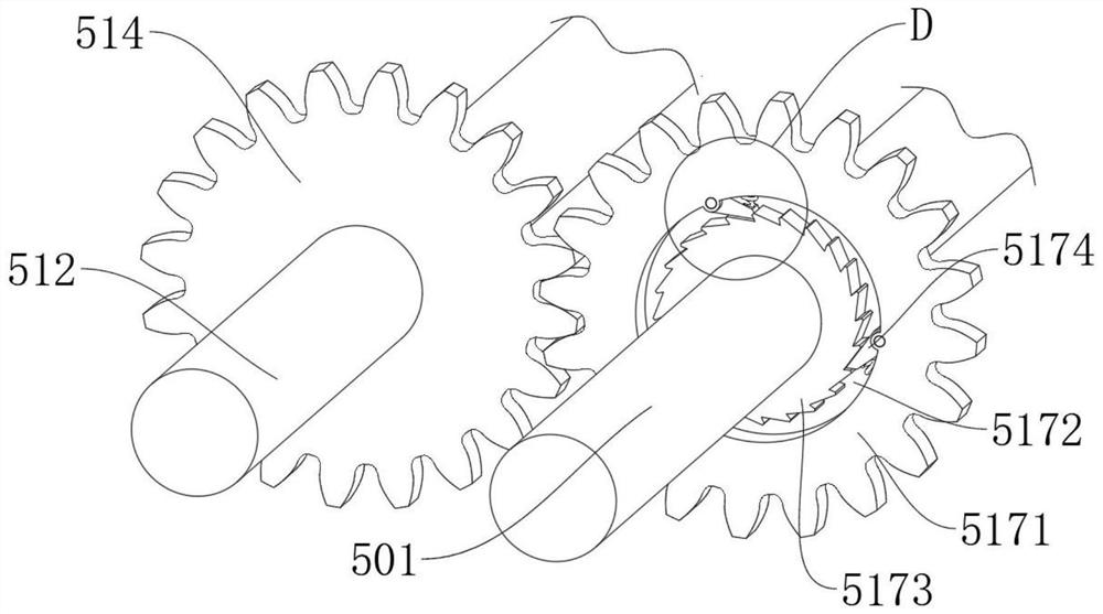
[0038] see Figure 5 , this embodiment is a further description of Embodiment 1, wherein the transmission device 511 includes a third transmission shaft 512 that is rotatably connected to the two support plates 101, and a first pulley 513 and a first pulley 513 are fixed on the third transmission shaft 512. The third gear 514, the first pulley 513 is sleeved with a belt 515, the belt 515 is sleeved with a second pulley 516 fixedly connected to the first transmission shaft 103, the third gear 514 is connected with transmission assembly 517 .
PUM
 Abstract
Description
Claims
Application Information
 - R&D
- Intellectual Property
- Life Sciences
- Materials
- Tech Scout
- Unparalleled Data Quality
- Higher Quality Content
- 60% Fewer Hallucinations
Browse by: Latest US Patents, China's latest patents, Technical Efficacy Thesaurus, Application Domain, Technology Topic, Popular Technical Reports.
© 2025 PatSnap. All rights reserved.Legal|Privacy policy|Modern Slavery Act Transparency Statement|Sitemap|About US| Contact US: help@patsnap.com


