Vehicle lower body structure

A body and vehicle technology, applied to the substructure, vehicle components, superstructure, etc., can solve the problems of deformation of the cabin, inability to collide with the load transfer dispersion, collapse of the lower side beam section, etc., to ensure the effect of impact energy absorption performance

Active Publication Date: 2022-02-18
MAZDA MOTOR CORP
View PDF9 Cites 0 Cited by
  • Summary
  • Abstract
  • Description
  • Claims
  • Application Information

AI Technical Summary

Problems solved by technology

[0014] That is, since the bending deformation of the side sill caused by the collision load is structurally suppressed, the inner component in the vehicle width direction of the collision load directly acts on the side sill, causing inversion deformation in which the side sill falls inward in the vehicle width direction.
When the side sill is deformed inwardly, shear stress acts on the joint (flange) formed by welding the outer panel and the inner panel of the side sill, and finally, the joint of the outer panel and the inner panel is cracked. And there is a concern that the section of the side beam will collapse
[0015] When the section of the side sill collapses, the collision load cannot be sufficiently transmitted and distributed to the rear of the vehicle body through the side sill, causing deformation of the cabin
In particular, in a vehicle with an enlarged wheel size, the front-rear length of the wheel house is enlarged, and it is difficult to ensure a crush area for absorbing impact at the front end portion of the side sill. Therefore, compared with a vehicle without an enlarged wheel size, Significant tendency for the side sill to buckle in small overlap collisions
[0016] In other words, there is still room for improvement in impact energy absorption performance in small overlap collisions

Method used


Image

  • Vehicle lower body structure
  • Vehicle lower body structure
  • Vehicle lower body structure

Examples


Embodiment 1

[0075] Below, based on Figure 1 to Figure 11 Example 1 of the present invention will be described.

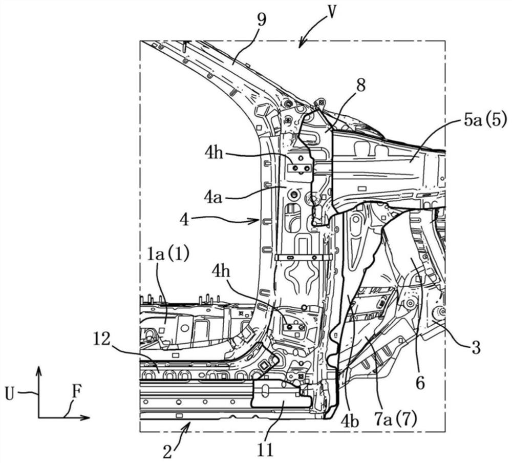
[0076] Such as figure 1 As shown, the vehicle V includes: a floor panel 1 forming a tunnel portion 1a and constituting the bottom surface of the vehicle compartment; a pair of left and right side sills 2 extending forward and backward; A dash panel (not shown), a pair of left and right front longitudinal frames 3 extending forward from the dash panel, a pair of left and right hinge pillars 4 extending vertically upward from the front ends of the pair of side sills 2, And a pair of left and right skirt reinforcements 5 extending forward from the upper end portions of the pair of hinge posts 4 and the like.

[0077] In this vehicle V, an impact energy absorbing mechanism is provided, and in the SORB (Small Overlap Rigid Barrier: Small Overlap Rigid Barrier) test, an obstacle and a portion (overlapping area) outside the front longitudinal frame 3 in the vehicle width direction ...

Embodiment 2

[0125] Next, based on Figure 12 , Figure 13 The reinforcing member 30A of the second embodiment will be described. In addition, the same code|symbol is attached|subjected to the same component as Example 1.

[0126] In Embodiment 1, the deformation suppressing portion 33 is composed of the first portion 33a, the third portion 33c perpendicular to the vehicle body front-rear direction, the second portion 33b, and the fourth portion 33d perpendicular to the vehicle width direction. In Embodiment 2, the deformation suppressing portion 33A is composed of a fifth portion 33e substantially perpendicular to the inner rear in the vehicle width direction.

[0127] Such as Figure 12 , Figure 13 As shown, the reinforcement member 30A has a front end reinforcement portion 31A, a deformation allowable portion 32A, and a deformation suppression portion 33A as main structural elements, and when a collision load toward the inner rear in the vehicle width direction is input to the fron...


PUM


Abstract

Provided is a vehicle lower body structure capable of sufficiently ensuring impact energy absorption performance during a small overlap collision, the vehicle lower body structure being provided with a rocker (2) that forms a first closed cross-section (C1) that extends in the front-rear direction of the vehicle body, and a reinforcing member (30) that is provided within the first closed cross-section (C1) and reinforces the front end portion of the rocker (2). The reinforcing member (30) has: a front end reinforcing section (31) that supports a collision load inputted to the front end portion of the rocker (2) toward the rear of the vehicle body; a deformation permitting section (32) that permits deformation of the rocker (2) toward the inside and the rear in the vehicle width direction when a collision load toward the inside and the rear in the vehicle width direction is input to the front end portion of the rocker (2); and a deformation suppression section (33) that suppresses deformation of the rocker (2) after the rocker (2) deforms inward and rearward in the vehicle width direction.

Description

technical field [0001] The present invention relates to an underbody structure of a vehicle including a side sill having a closed cross section extending in the front-rear direction of the vehicle body and a reinforcing member for reinforcing a front end portion of the side sill. Background technique [0002] Conventionally, it has been known that when an obstacle collides with a part (overlapping area of ​​25% or less) outside the front longitudinal frame in the vehicle width direction represented by the SORB (Small Overlap Rigid Barrier) test, that is, In a so-called small overlap collision, since the front wheels come into contact with the front end of the side sill, the hinge pillar falls toward the rear of the vehicle body. It is also known that when the hinge pillar falls toward the rear of the vehicle body, bending deformation occurs in the rocker due to a moment generated by the collision load concentrated in the rocker. [0003] Therefore, various technical solutio...

Claims


Application Information

Patent Timeline
IPC IPC(8): B62D21/15B62D25/20
CPCB62D21/15B62D25/20B62D25/025B62D25/04B62D27/023B62D21/152
Inventor 石川靖守田雄一山口雄作今城秀之三好克久西本允也
Owner MAZDA MOTOR CORP
Why Eureka
Try Eureka