Charging wire packaging system

A technology of packaging system and charging line, which is applied in the field of production and manufacturing, can solve the problems of low production efficiency, achieve a high degree of automation, reduce manual participation, and improve production efficiency

Active Publication Date: 2022-02-18
深圳市双龙智造科技有限公司
5 Cites 0 Cited by

AI-Extracted Technical Summary

Problems solved by technology

[0005] The purpose of the embodiments of the present invention is to provide a charging cable packaging system, which aims to solve the problem of winding the charging ca...

Method used

In the embodiment of the present invention, the driving assembly 800 is provided with one, and when the winding assembly 600 moves to the top of the driving assembly 800, the driving assembly 800 can drive the winding assembly 600 to work, which reduces the use of the driving assembly 800 and realizes In order to achieve continuous production, it leaves time for the unloading of coils wound into rolls, and the various actions are closely coordinated.
The present invention can form the protective cover sheet into a protective cover by setting the protective cover forming device, the charging cable can be wound into a circle by the charging cable winding device, and the mechanical arm can be used to grab the protective cover and set it on the charging coil , complete the automatic packaging of the charging cable. The invention has a high degree of automation, reduces manual participation and improves production efficiency.
[0074] In the embodiment of the present invention, the position of the protective cover piece 108 can be adjusted through the expansion and contraction of the three-axis cylinder 501 itself, so as to prevent the protective cover piece 108 from running off during the pushing process. At the same time, through the expansion and contraction of t...

Abstract

The invention belongs to the technical field of production and manufacturing, and particularly relates to a charging wire packaging system, which comprises a protective sleeve forming device, a charging wire winding device and a mechanical arm; the protective sleeve forming device is used for manufacturing a protective sleeve sheet material into a protective sleeve; the charging wire winding device is used for winding a charging wire into a circle; and the mechanical arm is used for sleeving the charging wire which is wound into a circle with the protective sleeve. According to the charging wire packaging system, the protective sleeve sheet can form a protective sleeve through the protective sleeve forming device, the charging wire can be wound into a circle through the charging wire winding device, the protective sleeve can be grabbed through the mechanical arm to be arranged on a charging winding roll in a sleeving mode, and automatic packaging of the charging wire is completed. The system is high in automation degree, manual participation is reduced, and the production efficiency is improved.

Application Domain

Technology Topic

Manufacturing engineeringProtection KIT +3

Image

  • Charging wire packaging system
  • Charging wire packaging system
  • Charging wire packaging system

Examples

  • Experimental program(1)

Example Embodiment

[0028] In order to make the object, technical solution and advantages of the present invention clearer, the present invention will be further described in detail below in conjunction with the accompanying drawings and embodiments. It should be understood that the specific embodiments described here are only used to explain the present invention, not to limit the present invention.
[0029] The specific implementation of the present invention will be described in detail below in conjunction with specific embodiments.
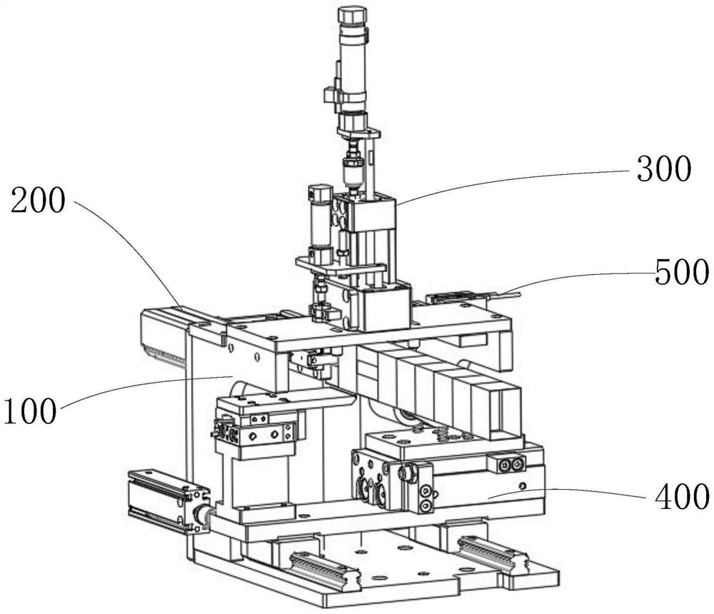
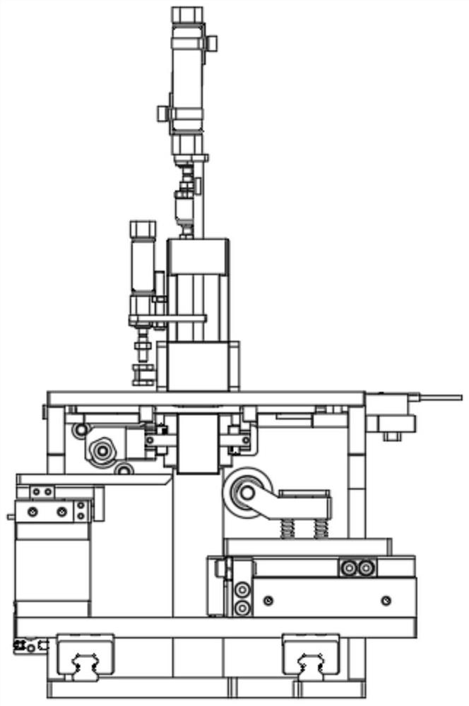
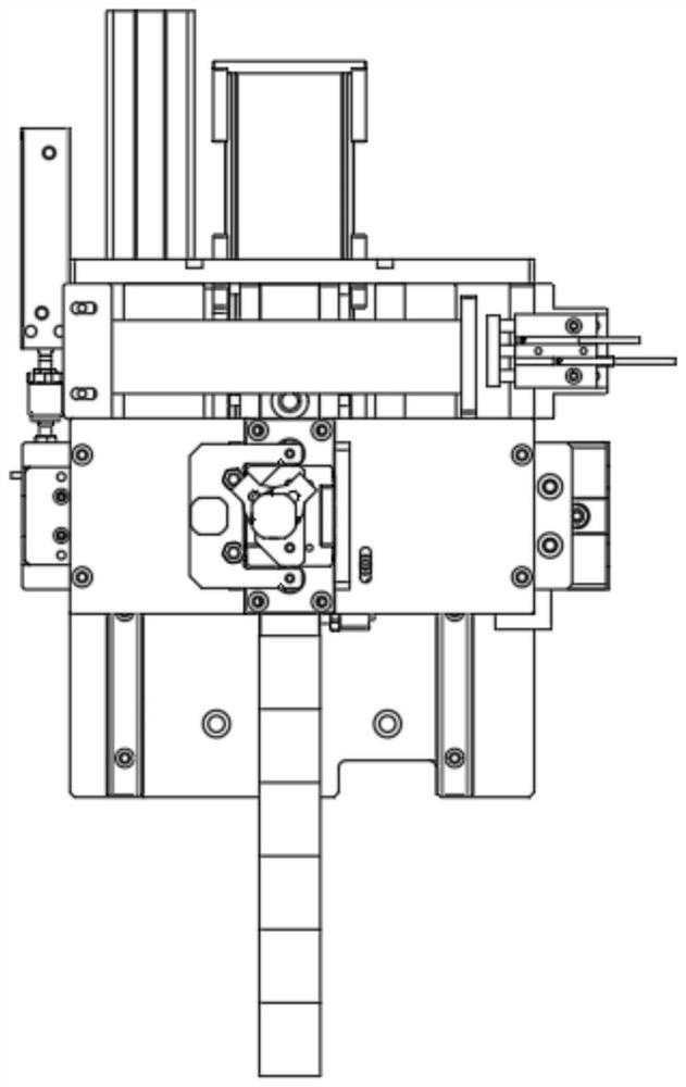
[0030] As shown in the figure, an embodiment of the present invention provides a charging cable packaging system, which includes a protective sleeve forming device, a charging cable winding device, and a mechanical arm;
[0031] The protective sheath forming device is used to make the protective sheath sheet material into a protective sheath;
[0032] The charging wire winding device is used to wind the charging wire into a circle;
[0033] The mechanical arm is used for sheathing the protective cover on the charging cable wound into a circle.
[0034] In the embodiment of the present invention, the protective cover forming device makes the protective cover sheet material into a protective cover, the charging wire winding device is used to wind the charging cable into a circle, and then the mechanical arm grabs the protective cover and sets it on the coiled On the final charging coil, and remove the charging coil from the charging cable winding device, complete the packaging of the charging cable. In the embodiment of the present invention, the specific structure of the mechanical arm is not described in detail, and any type of existing mechanical arm may be used. In terms of layout, it only needs to satisfy that the mechanical arm can grab the protective cover from the unloading position of the protective cover forming device, and drive the protective cover to move to the unloading position of the charging cable winding device, and then complete the packaging of the charging cable Take it off from the charging cable winding device and put it on the finished product collecting device.
[0035] In the present invention, the protective cover sheet can be formed into a protective cover by setting the protective cover forming device, the charging cable can be wound into a circle by the charging cable winding device, and the protective cover can be grasped and set on the charging winding by the mechanical arm. Automated packaging of charging cables. The invention has a high degree of automation, reduces manual participation and improves production efficiency.
[0036] In one embodiment of the present invention, the protective cover forming device includes a frame 100 and a pusher assembly 200 , a fold-down assembly 300 , a sealing assembly 400 and a positioning assembly 500 arranged on the frame 100 ;
[0037] The frame 100 is used for installing and fixing the pusher assembly 200, the fold-down assembly 300 and the sealing assembly 400;
[0038] The pusher assembly 200 is used to push the sheet material 108 of the protective cover to the working position of the fold-down component 300 , and push the folded-down protective cover away from the working position of the fold-down component 300 ;
[0039] The sealing assembly 400 is used for sealing the protective cover folded down;
[0040] The positioning component 500 is used for positioning the protective cover sheet 108 .
[0041] In the embodiment of the present invention, in the embodiment of the present invention, the mobile phone charging cable protective cover is used for fixing and protecting the shape of the mobile phone charging cable after it is coiled. It is a rectangular parallelepiped columnar structure with openings at both ends. Sealing is formed, and the mobile phone charging cable protective cover forming device provided by the present invention produces a protective cover from the protective sheet through the cooperation of the above-mentioned various components.
[0042] In the embodiment of the present invention, the frame 100 is used for mounting and fixing other components. In the present invention, the other components are all arranged on the frame 100 , and the components are connected as a whole through the frame 100 .
[0043] In the embodiment of the present invention, the pusher assembly 200 is used for pushing the protective cover piece 108 and the folded down protective cover. Preferably, the two pushing processes in the present invention are driven by the same pushing action, that is, two pushing process simultaneously.
[0044] In the embodiment of the present invention, the fold-down component 300 is used to fold down the protective cover sheet 108 on both sides. is the center of symmetry of the protective sheath sheet 108 length.
[0045] In the embodiment of the present invention, the sealing assembly 400 is used to bend the protective cover from a zigzag shape to a square shape, and further, it can also be used to paste and fix the opening of the protective cover bent into a square shape.
[0046] In the embodiment of the present invention, the positioning assembly 500 can fix the position of the protective sheath sheet 108, and the two ends of the protective sheath sheet 108 can slide along the edge of the positioning assembly 500 when pushing the material, so as to prevent run-off during the pushing process. Partial.
[0047] like Figure 1-9 As shown, in one embodiment of the present invention, the frame 100 includes a first bottom plate 101, and the opposite sides of the first bottom plate 101 are respectively provided with a first vertical plate 103 and a second vertical plate 113, and the first vertical plate 103 It is also arranged on the back plate 105 between the second vertical plate 113, and the first vertical plate 103, the second vertical plate 113 and the back plate 105 are arranged in a flat shape in a plan view;
[0048] The top of the first vertical plate 103 and the second vertical plate 113 is provided with a forming top plate 110, and the middle part of the forming top plate 110 is provided with a through hole, and the fold-down assembly 300 folds down the protective cover sheet 108 through the through hole;
[0049] The side of the back plate 105 facing the forming top plate 110 is provided with a forming jig 106, and the protective cover is sleeved on the surface of the forming jig 106 after being formed, and is pushed along the forming The length direction movement of jig 106;
[0050] The side of the back plate 105 facing the forming top plate 110 is provided with a first supporting plate 107 and a second supporting plate 112, and the first supporting plate 107 and the second supporting plate 112 are respectively arranged on two sides of the forming jig 106. , and the top surfaces of the first supporting plate 107 and the second supporting plate 112 are in close contact with the bottom of the forming top plate 110 , and are in the same plane as the top surface of the forming jig 106 .
[0051] In the embodiment of the present invention, the first vertical plate 103, the second vertical plate 113 and the back plate 105 are all perpendicular to the first bottom plate 101, the first vertical plate 103 and the second vertical plate 113 are all arranged in a Γ shape, and the top plates overlap On the right side of the top of the Γ shape. The forming jig 106 is arranged as a column with a rectangular cross section, located in the middle of the top surface of the back plate 105, and arranged horizontally. The forming jig 106 is also provided with a retaining column 111; The support seat 114 , the side of the support seat 114 is in close contact with the back plate 105 .
[0052] In the embodiment of the present invention, both the first supporting board 107 and the second supporting board 112 are connected with the back board 105, the front end of the first supporting board 107 is connected with the first vertical board 103, and the front end of the second supporting board 112 is connected with the second Riser 113 is connected. The top of the first vertical plate 103 is provided with an adjustment bar 109, and the adjustment bar 109 is connected with the first vertical plate 103 through a waist-shaped hole, and the relative position between the first vertical plate 103 is adjustable in the horizontal direction, making it close to or away from Protective sheath sheet 108 . When in use, both ends of the protective sheath sheet 108 are placed on the two pallets, and the middle part of the protective sheath sheet 108 is placed on the top of the molding jig 106 .
[0053] In one embodiment of the present invention, the pusher assembly 200 includes a first driving member 204 arranged on the back plate 105 and a pusher member arranged on the molding jig 106; the first driving member 204 drives the pusher to push the protective cover piece 108 to the working position of the fold-down assembly 300, and pushes the folded-down protective cover away from the working position of the fold-down component 300;
[0054] The first driver 204 adopts a telescopic cylinder, and the telescopic shaft of the telescopic cylinder passes through the back plate 105 toward the side where the forming jig 106 is located;
[0055] The pusher includes two first linear slide rails 102 arranged in parallel, the two ends of the two first linear slide rails 102 are connected to each other by push strips 208 to form a rectangular structure, and the two first linear slide rails 102 are opposite to each other. One side is slidingly connected with a guide rail mounting plate 206, and the two guide rail mounting plates 206 are respectively fixedly connected with the two sides of the forming fixture 106; the first driving member 204 is fixedly connected with the middle part of one of the first linear slide rails 102, Pushing blocks 203 are arranged in the middle of the first linear slide rails 102 , and the top surface of the pushing block 203 is higher than the top surface of the molding jig 106 .
[0056] In the embodiment of the present invention, when the pushing member is working, the protective sheath sheet 108 waiting to be folded down is pushed to the bottom of the folded down assembly 300, and at the same time, the folded down protective cover is pushed away from the working position of the folded down assembly 300 , both processes are driven by the same driver.
[0057] In the embodiment of the present invention, the pusher bar 208 is connected to the first linear slide rail 102 through the guide rail connecting block 207; the pusher block 203 is fixedly connected to the first linear slide rail 102; There are a first cylinder joint 201 and a joint buckle 202 for connecting with an air source. During work, the first driving member 204 drives the first linear slide rail 102 to slide relative to the guide rail mounting plate 206, and uses the pusher block 203 to push the protective cover sheet 108 to be folded down to the working area of ​​the folded down assembly 300, while using The pushing bar 208 pushes the side edge of the protective cover that has been folded down to push it out of the working area of ​​the folded down assembly 300, and then retreats and waits for the next cycle.
[0058] In the embodiment of the present invention, further, a through groove is opened in the middle of the forming jig 106, and the through groove is opened along the length direction of the forming jig 106, and is located on the side of the first linear slide rail 102 close to the forming jig 106. The push strip 208 passes through the through groove.
[0059] In one embodiment of the present invention, the folding down assembly 300 includes a folding sleeve fixing seat 301 , a guide rod 304 , a limit block 305 , a first pen-shaped cylinder 307 and a folding sleeve plate 310 ;
[0060] The folding sleeve fixing seat 301 is arranged on the top of the forming top plate 110, the folding sleeve fixing base 301 is connected with the first pen-shaped cylinder 307 through a guide rod 304, and the guide rod 304 passes through the limit block 305;
[0061] The output shaft of the first pen-shaped cylinder 307 is connected to the stop block 305, and the two sides of the stop block 305 are respectively provided with a folded sleeve plate 310, and the bottom of the folded sleeve plate 310 is slidably connected with the folded sleeve holder 301 ; After pressing down, the inner sides of the two folded sleeves 310 are in close contact with one side of the forming fixture 106 respectively;
[0062] The folding down assembly 300 also includes a limiting plate 315, which is located at the bottom of the folding sleeve fixing seat 301, and its outer contour size is smaller than the opening on the forming top plate 110;
[0063] The limit plate 315 is connected with a lifting shaft 316, and the lifting shaft 316 passes through the folding sleeve fixing seat 301 and is connected with the second pen-shaped cylinder 309, and the telescopic shaft of the second pen-shaped cylinder 309 is fixedly connected with the folding sleeve fixing seat 301 , the second pen-shaped cylinder 309 drives the limiting plate 315 to press down to fix the protective cover piece 108 on the top of the molding jig 106 .
[0064] In the embodiment of the present invention, the folding sleeve fixing seat 301 is fixedly connected with the forming top plate 110, and can be connected by screws, welding, etc. The two sides are provided with a chute that accommodates the folding cover plate 310 to pass through. When the first pen-shaped cylinder 307 stretches, the stop block 305 connected to its output shaft moves, driving the folding plate 310 connected to the stop block 305 to move up and down, thereby bending both sides of the protective sheath sheet 108 . A linear bearing 302 and a snap spring 303 are disposed between the guide rod 304 and the folding sleeve fixing seat 301 ; the first pen-shaped cylinder 307 is disposed with a floating joint 306 .
[0065] In the embodiment of the present invention, under the drive of the second pen-shaped cylinder 309, the limit plate 315 can move up and down, and when it moves down, it abuts against the top of the forming jig 106 to press the protective sheath sheet 108 against the forming jig. Tool 106, then the first pen-shaped cylinder 307 drives the folding plate 310 to complete the downward folding action. The second pen-shaped cylinder 309 is provided with a second cylinder connector 312; the second pen-shaped cylinder 309 is connected with the lifting shaft 316 through the cylinder support block 311, and the output shaft of the second pen-shaped cylinder 309 is also provided with an adjustment screw 308, which can adjust the output shaft The length; the output shaft end of the second pen-shaped cylinder 309 is connected and fixed with the folding sleeve fixing seat 301 through the cylinder mounting seat 314; the joint limit block 313 is provided on the cylinder mounting seat 314.
[0066] In one embodiment of the present invention, the sealing assembly 400 includes a cross-folding assembly disposed at the bottom of the forming jig 106 , the cross-folding assembly includes a second driving element 403 and an output device disposed on the second driving element 403 The moving plate 404 at the end, the second driving member 403 is used to drive the moving plate 404 to move horizontally; the top surface of the moving plate 404 is flush with the bottom surface of the molding jig 106 .
[0067] The sealing assembly 400 also includes a third driving member 416, the third driving member 416 is provided with a connecting plate 415, the connecting plate 415 is provided with a sealing moving block 414, and the sealing moving block 414 is provided with a pair of connecting arms inclined forward, connected A shaft 406 is rotatably connected between the arms, and a shaft roller 405 is sheathed on the shaft 406. When the shaft roller 405 abuts against the forming jig 106, the shaft roller 405 is pressed down.
[0068] In the embodiment of the present invention, the second driving member 403 can be a cylinder, the output shaft of the cylinder is provided with a moving plate 404, the upper end surface of the moving plate 404 is coplanar with the lower surface of the molding jig 106, and the second driving member 403 Drive the moving plate 404 to horizontally fold the side of the folded down protective cover.
[0069] In the embodiment of the present invention, the third driving member 416 can be an air cylinder, and the cylinder drives the shaft roller 405 to move to the forming jig 106, and the shaft roller 405 can use an adhesive roller or a heating roller, and the protective roller is sealed by gluing or heat sealing. Set of seals. In this embodiment, the sealing moving block 414 and the connecting plate 415 are fixedly connected through the cover plate 409, the four corners of the cover plate 409 are provided with connection holes, and a buffer ring 410 is provided between the cover plate 409 and the sealing moving block 414; An oil-free bushing 411 and a spring column 412 are arranged in the hole facing the connecting hole of the moving block 414 and the cover plate, and a spring 413 is arranged between the sealing moving block 414 and the connecting plate 415 . When the shaft roller 405 is pressed down by force, the spring 413 is compressed to realize elastic connection, so that the shaft roller 405 can maintain a certain pressure. The third driving member 416 is mounted on the guide rail connecting plate 401 , the other end of the guide rail connecting plate 401 is provided with the cylinder mounting plate 402 , and the second driving member 403 is provided on the cylinder mounting plate 402 .
[0070] In the embodiment of the present invention, a deep groove ball bearing 407 and a retaining ring 408 are further arranged between the rotating shaft 406 and the shaft roller 405 .
[0071] In one embodiment of the present invention, the positioning assembly 500 includes a three-axis cylinder 501 and a positioning rod 502;
[0072] The three-axis cylinder 501 is located on the top of a vertical plate, and is installed on the three-axis cylinder installation block 504 through the three-axis cylinder fixing block 503, and the position between the three-axis cylinder 501 and the three-axis cylinder installation block 503 is adjustable;
[0073] The output shaft of the three-axis cylinder 501 is provided with a positioning rod 502 , one end of the positioning rod 502 is inserted between the supporting plate and the forming top plate 110 , and one side of the positioning rod 502 abuts against the protective sheath sheet 108 .
[0074]In the embodiment of the present invention, the position of the protective cover piece 108 can be adjusted through the expansion and contraction of the three-axis cylinder 501 itself, so as to prevent the protective cover piece 108 from running off during the pushing process. At the same time, through the expansion and contraction of the three-axis cylinder 501 or the adjustment of the position of the three-axis cylinder 501 relative to the three-axis cylinder mounting block 504, different sizes of sheet materials can be applied, which improves the applicability.
[0075] like Figure 10-16 As shown, in one embodiment of the present invention, the charging cable winding device includes a winding assembly 600 , a switching assembly 700 , a driving assembly 800 and a guiding assembly 900 ;
[0076] The wire winding assembly 600 is provided with two groups for winding the charging wire into a circle;
[0077] The switching assembly 700 is used to switch the positions of two sets of winding assemblies 600, so that the winding assembly 600 is docked with or separated from the driving assembly 800;
[0078] The driving assembly 800 is used to drive the winding assembly 600 to wind the charging wire into a circle;
[0079] The guide assembly 900 adjusts the entanglement position of the charging cable by moving up and down.
[0080] In the embodiment of the present invention, in the embodiment of the present invention, the wire winding assembly 600 is used to wind the charging wire into a coil, specifically a coil wound into a single layer in the present invention. Two sets of winding assemblies 600 are provided. The two sets of winding assemblies 600 in the present invention work alternately to wind the charging line and unload the wound coil at the same time, thereby realizing continuous production.
[0081] In the embodiment of the present invention, the switch assembly 700 is used to switch the working positions of the two sets of winding assemblies 600. In one of the working positions, the winding assembly 600 is docked with the driving assembly 800, and the driving assembly 800 can drive the winding assembly 600 to rotate. .
[0082] In the embodiment of the present invention, the drive assembly 800 is provided with one. When the winding assembly 600 moves above the drive assembly 800, the drive assembly 800 can drive the winding assembly 600 to work, which reduces the use of the drive assembly 800 and realizes continuous Production leaves time for the unloading of coils wound into rolls, and the various actions are closely coordinated.
[0083] In the embodiment of the present invention, the guide assembly 900 is used to guide the charging wire to be wound into the position of the winding assembly 600, so as to prevent the charging wire from stacking and winding on the winding assembly 600, and can form a single-layer winding form with good product consistency. In the embodiment of the present invention, the guide assembly 900 may not be directly connected with other components as a whole, or may be fixedly connected with the second bottom plate 709 of the switch assembly 700 .
[0084] In one embodiment of the present invention, the switching assembly 700 includes a second bottom plate 709, the bottom surface of the second bottom plate 709 is provided with a driving motor, and the output shaft of the driving motor passes through the second bottom plate 709 and is arranged on the top of the second bottom plate 709. The hollow rotary platform 707 on the surface is connected;
[0085] The top of the hollow rotating platform 707 is provided with a turntable 701, and the drive motor is connected to the turntable 701 for driving the turntable 701 to rotate; the winding assembly 600 is arranged on the turntable 701;
[0086] The winding assembly 600 includes a rotating part and a transmission part;
[0087] The rotating part includes a coiled material platform 615, which is set on the top of the turntable 701 of the switching assembly 700; the coiled material platform 615 is provided with two arc-shaped tiles driven by a thin cylinder 617 to move closer or farther away. slice 601;
[0088] The transmission part is arranged at the bottom of the turntable 701, and is used to drive the coil platform 615 to rotate;
[0089] The transmission part includes a bearing seat 607, the bearing seat 607 is arranged at the bottom of the turntable 701, and the coil material central axis 614 is rotated inside the bearing seat 607, and the top of the coil material central axis 614 is connected with the coil material platform. 615 connection;
[0090] An isolating ring 608 is arranged between the central shaft 614 of the coil material and the bearing seat 607, and an oil seal 613 is arranged on the outer circumference of the isolating ring 608. The isolating ring 608 is connected with the angular contact bearing 609, and the angular contact bearing 609 is arranged on the bearing seat 607. Inside; the lower end of the bearing seat 607 is provided with a locknut 612, and the coil center axis 614 passes through the locknut 612 and extends out of the bearing seat 607; the lower end of the coil center axis 614 is fixedly connected with a coil center axis holder 611 , two cam bearings 610 are arranged below the coil material central axis holder 611 .
[0091] In the embodiment of the present invention, the second bottom plate 709 is arranged in a rectangular shape, and a through hole is opened in the center of the second bottom plate 709, through which the output shaft of the driving motor passes, and a transmission mechanism, such as a gear, can be arranged in the hollow rotating platform 707 Transmission mechanism, etc., used for reversing, deceleration, etc. A second air joint 710 is provided on the turntable 701 ; the hollow rotating platform 707 is connected to the second bottom plate 709 through the hollow rotating platform mounting seat 711 .
[0092] In the embodiment of the present invention, the turntable 701 is set in a circular shape, the output shaft of the driving motor is connected to the center of the turntable 701 , and the two winding assemblies 600 are arranged on the turntable 701 and are symmetrical about the rotation center of the turntable 701 .
[0093] In the embodiment of the present invention, a chute is provided on the top surface of the coil platform 615, and the thin cylinder 617 drives the two arc-shaped tiles 601 to slide along the chute, so that the two arc-shaped tiles 601 can approach or move away. When working, the two arc-shaped tiles 601 keep a certain distance, and the coil platform 615 rotates to wind the charging cable onto the two tiles. The last charging line is easy to escape from the arc tile 601 from bottom to top. The thin cylinder 617 is installed and fixed through the thin cylinder connecting seat 602 and the thin cylinder mounting block 616; the thin cylinder 617 is connected to the air source through the first air joint 604; the edge of the coil platform 615 is provided with a stopper 605; the thin cylinder The connecting seat 602 is connected to the arc tile 601 through the arc fixing block 603 and the cushion block 618. The arc fixing block 603 is provided with an arc surface that is close to the inner side of the arc tile 601, and the drive of the thin cylinder 617 The shaft is connected with the spacer 618, which is arranged in the hole provided on the thin cylinder connection seat 602, and the spacer 618 is connected with the arc-shaped fixing block 603 by screws, and the screws pass through the arc-shaped tiles 601.
[0094] In the embodiment of the present invention, the arc-shaped tiles 601 can form a cylindrical surface after being close together, and at least one clamping member 620 is provided on the opposite side of the arc-shaped tiles 601, and the charging head of the charging line can be placed on the clamping member. At 620 , the coil platform 615 rotates so that the charging cable can be wound on the arc-shaped tile 601 .
[0095] In the embodiment of the present invention, the arc-shaped tiles 601 can form a cylindrical surface after being close together, and at least one arc-shaped fixing block 603 is provided on the opposite side of the arc-shaped tiles 601, and the charging head of the charging line can be placed on the arc-shaped In the gap between the fixed block 603 and the arc tile 601 , the coil platform 615 rotates so that the charging cable can be wound on the arc tile 601 .
[0096] In the embodiment of the present invention, the turntable 701 is provided with a through hole facing the middle of the coil material platform 615, and the coil material central axis 614 passes through the through hole to connect with the coil material platform 615, and the coil material central axis 614 and the bearing seat 607 An isolation cup, an oil seal 613 and an angular contact bearing 609 are arranged from the inside to the outside, and are located at the bottom of the bearing seat 607 , and a locknut 612 is arranged on the central shaft 614 of the coil. A first pipe joint 606 is also arranged on the bearing seat 607 .
[0097] In the embodiment of the present invention, the bottom of the central shaft 614 of the coil is provided with a central deck of the coil, and two cam bearings 610 are arranged below the central deck of the coil. bilateral symmetry.
[0098] In one embodiment of the present invention, an annular track 708 is provided on the upper side of the second bottom plate 709 of the switching assembly 700, and the center of the annular track 708 is directly opposite to the center of the turntable 701;
[0099] The cross-section of the circular track 708 is L-shaped, and the two cam bearings 610 below the central shaft holder 611 of the winding assembly 600 abut against the circular track 708;
[0100] The driving assembly 800 includes a track connection seat 801, which is arranged on the upper side of the second bottom plate 709 of the switching assembly 700, and an arc-shaped extending groove is opened on the track connection seat 801, and the two ends of the groove are aligned with the The circular track 708 is docked to form a complete circular track 708;
[0101] The second bottom plate 709 of the switching assembly 700 is facing the position of the track connecting seat 801 with a through hole, and a motor rotating block 803 is arranged in the through hole, and the top of the motor rotating block 803 is fixedly connected with the described track connecting seat 801, and the motor rotates The outer circumference of the block 803 is rotatably connected with the servo motor mounting plate 804 , and a planetary reducer 805 and a servo motor 806 are arranged under the servo motor mounting plate 804 , and the output shaft of the servo motor 806 is connected with the motor rotating block 803 .
[0102] In the embodiment of the present invention, when the turntable 701 rotates, the two cam bearings 610 abut against the side of the L-shaped annular track 708, so that after the winding assembly 600 rotates through any angle with the turntable 701, it is relatively The orientation remains unchanged all the time, so that the two cam bearings 610 and the drive assembly 800 can be correctly docked in the next working cycle.
[0103] In the embodiment of the present invention, the annular track 708 is provided with a notch, and a track connecting seat 801 is arranged at the position of the notch, and an arc-shaped groove is arranged on the track connecting seat 801, which can accommodate two cam bearings 610 at the same time . The track connecting seat 801 is provided with a cylindrical shape, and is rotatably connected with the second bottom plate 709 . When the turntable 701 rotates, it can respectively drive the cam bearings 610 of the two winding assemblies 600 into the grooves of the track connecting seat 801 , and the rotation of the track connecting seat 801 can drive the winding assembly 600 to rotate.
[0104] In the embodiment of the present invention, the output shaft of the servo motor 806 drives the motor rotating block 803 to rotate through the planetary reducer 805 , thereby driving the track connecting seat 801 to rotate.
[0105] In one embodiment of the present invention, a first proximity switch 802 is provided on the upper side edge of the second bottom plate 709 of the switch assembly 700 , and the first proximity switch 802 is used to detect the rotation angle of the rail connecting seat 801 .
[0106] In the embodiment of the present invention, the first proximity switch 802 can be used to detect the rotation angle of the track connecting seat 801, which can be changed by setting protrusions or grooves on the outer circumference of the track connecting seat 801 to change the receiving angle of the first proximity switch 802. The strength of the reflected signal is detected.
[0107] In one embodiment of the present invention, a second proximity switch 705 is provided on the lower edge of the turntable 701 , and the second proximity switch 705 is used for detecting the rotation angle of the turntable 701 .
[0108] In the embodiment of the present invention, the second proximity switch 705 is used to detect the rotation angle of the turntable 701, so as to realize the positioning of the winding assembly 600. Correspondingly, several reflection points can be set on the hollow rotating platform for the reflection of the transmitted signal. , so as to realize the detection. In the embodiment of the present invention, taking the second proximity switch 705 as an example, the proximity switch includes a proximity switch sensing block 702 , a limit block 703 for protecting the proximity switch, and a proximity switch sensing piece 704 .
[0109] In one embodiment of the present invention, four outer corners of the top surface of the second bottom plate 709 of the switching assembly 700 are provided with support columns for installation and connection of the device.
[0110] In the embodiment of the present invention, the support column can be used for the connection of the housing, and can also be used for the installation and fixation of the device, etc. This is an optional specific usage mode, which is not specifically limited in the embodiment of the present invention. The support columns include a first support column 706 .
[0111] In one embodiment of the present invention, the guiding assembly 900 includes a lifting table 901 and a lifting mechanism;
[0112] The lifting platform 901 is provided with an arc-shaped gap on one side edge facing the winding assembly 600, and the side edge away from the winding assembly 600 is rolled down;
[0113] A strut 909 is connected under the lifting platform 901, and the strut 909 passes through the screw motor fixing plate 908, and the bottom of the strut 909 is connected with the supporting plate 905; the screw motor fixing plate 908 is provided with a screw motor 904, and the screw motor The output shaft of 904 is connected with a screw mandrel, which is threadedly connected with the supporting plate 905, and the lifting table 901 is driven to move up and down by the screw mandrel motor 904.
[0114] In the embodiment of the present invention, when winding the wire, one end of the charging wire is clipped into the clamping member 620, and the charging wire is placed on the lifting platform 901. During the winding process, the lifting platform 901 moves upward at a constant speed to guide the charging wire from bottom to bottom. Winding on the arc-shaped tile 601 to form a single-layer coil. Optionally, the closer the distance between the arc-shaped notch of the lifting platform 901 and the arc-shaped tile 601 is, the more reliable the guiding effect is; the specific distance is optional, and is not specifically limited in this embodiment of the present invention.
[0115] In the embodiment of the present invention, the screw motor fixing plate 908 is connected to the support rod 909 through a linear bearing 903; the third proximity switch 907 is arranged under the screw motor fixing plate, and the third proximity switch is arranged on the proximity switch mounting piece 906 on.
[0116] The above descriptions are only preferred embodiments of the present invention, and are not intended to limit the present invention. Any modifications, equivalent replacements and improvements made within the spirit and principles of the present invention should be included in the protection of the present invention. within range.

PUM

no PUM

Description & Claims & Application Information

We can also present the details of the Description, Claims and Application information to help users get a comprehensive understanding of the technical details of the patent, such as background art, summary of invention, brief description of drawings, description of embodiments, and other original content. On the other hand, users can also determine the specific scope of protection of the technology through the list of claims; as well as understand the changes in the life cycle of the technology with the presentation of the patent timeline. Login to view more.

Similar technology patents

Classification and recommendation of technical efficacy words

  • Reduce manual involvement
  • High degree of automation

Full-automatic flexible assembly line of light emitting diode (LED) bulb lamp

InactiveCN102896494AIncreased reliability and automationHigh degree of automationAssembly machinesLight sourceStructure based
Owner:SHANGHAI RADIO EQUIP RES INST
Why Eureka
Try Eureka