A Formwork Supporting System of Adjustable Elevation Combined Buckle Frame Using Micro-Bump Technology

A micro-bump and combined technology, which is applied to the accessories of scaffolding, building structure support, building structure support, etc., can solve the problems that are difficult to match with multi-variant building structures, the application limitations of ring-type scaffolding, and the modulus of ring-type scaffolding Fixing and other problems, to increase convenience and accuracy, prevent bolt loss, and improve bearing capacity

Active Publication Date: 2022-05-24
THE THIRD CONSTR ENG CO LTD OF CHINA CONSTR SECOND ENG BUREAU
View PDF5 Cites 1 Cited by
  • Summary
  • Abstract
  • Description
  • Claims
  • Application Information

AI Technical Summary

Problems solved by technology

[0003] The modulus of the buckle scaffolding is relatively fixed, and it is difficult to match the multi-variant building structure. The buckle frame is limited by the modulus. When the length of the engineering structure does not meet the modulus requirements and in some special parts, the application of the buckle scaffold is limited.
For example, when using double-C steel supporting beams, due to the mismatch of modulus, a jacking is required on the double-C steel foundation, and the main keel is placed on the jacking, which will cause double main keel + jacking, and waste materials

Method used


Image

  • A Formwork Supporting System of Adjustable Elevation Combined Buckle Frame Using Micro-Bump Technology
  • A Formwork Supporting System of Adjustable Elevation Combined Buckle Frame Using Micro-Bump Technology
  • A Formwork Supporting System of Adjustable Elevation Combined Buckle Frame Using Micro-Bump Technology

Examples


Embodiment Construction

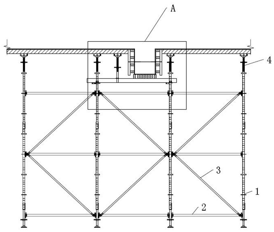
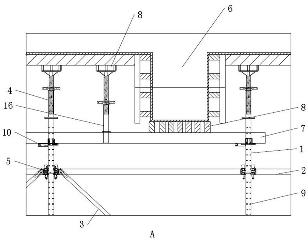
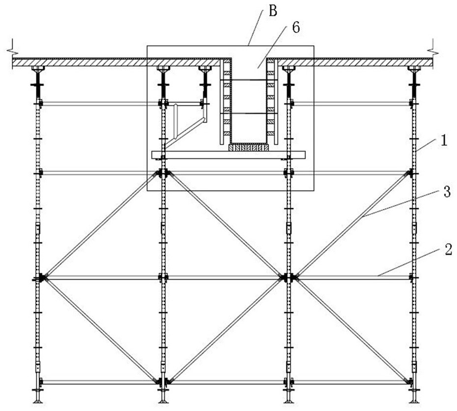
[0043] as Figure 1 and Figure 2 As shown, the present invention is an adjustable elevation combination disc buckle frame support system using micro-bump technique comprising a multi-row spacing uniformly set pole 1, connecting adjacent two rows of poles 1 crossbar 2, connecting each row of adjacent poles 1 longitudinal rod and connecting the vertical rod 1 and the bevel rod connected to the frame formed by the pole 1 and the crossbar 2, each row of pole 1 interval evenly arranged multiple roots, the upper end of the pole 1 is threaded with a top bracket 4, the top bracket 4 is used to install the keel 8 support template; the crossbar 2 and the longitudinal rod are set in multiple intervals along the height direction of the pole 1, Crossbar 2, longitudinal bar and diagonal bar 3 are fixed by latch connection with ordinary disc 5 fixed to pole 1, respectively.

[0044]Adjacent pole 1 at the bottom of the structural beam 6 is provided with a double C-beam 7 for supporting the structu...


PUM


Abstract

The invention discloses an adjustable-elevation combined plate buckle frame formwork support system using micro-bump technology, which includes a plurality of rows of vertical rods arranged at intervals, a horizontal rod connecting two adjacent rows of vertical rods, and a horizontal rod connecting each row of adjacent vertical rods. The vertical rods of the rods and the oblique rods connected in the frame formed by the vertical rods and the horizontal rods, between the adjacent vertical rods, there are double C-shaped steels at the bottom of the structural beams for supporting the bottom mold of the structural beams, and multiple A group of protruding points arranged at intervals along its length direction, and each group of protruding points is arranged at intervals along the circumferential direction of the pole; a disc buckle frame disc is arranged at the installation position of the C-shaped steel on the pole, and the disc buckle frame disc is supported on the C The bottom of the section steel; the disk of the buckle rack includes an upper half disk and a lower half disk, one end of which is hinged, and the other end is detachably connected by a connecting component; the inner openings of the upper half disk and the lower half disk are formed with The cylinder wall is provided with concave points matching with the convex points on the vertical rod. The application has the advantages of adjustable height, strong applicability, material saving and matching with different building structures.

Description

Technical field [0001] The present invention relates to the technical field of disc buckle scaffolding, in particular to a modulated elevation combined disc buckle frame support system using micro-bump technique. Background [0002] In recent years, with the development of scaffolding technology, different forms of scaffolding have been popularized and applied in the engineering construction process, in these scaffolding, disc buckle scaffolding due to reasonable structural stress, safe and reliable, good stability, has been vigorously promoted. [0003] Disc buckle scaffolding its module is relatively fixed, it is difficult to match more to become a building structure, the disc buckle frame is limited by the modulus, when the length of the engineering structure does not meet the modulus requirements and in some special parts, the application of the disc buckle scaffolding is limited. For example, when using a double C steel support beam, due to a modulus mismatch, a vertical top...

Claims


Application Information

Patent Timeline
Patent Type & Authority Patents(China)
IPC IPC(8): E04G1/02E04G1/12E04G5/00E04G5/06E04G5/16E04G7/30
CPCE04G1/02E04G1/12E04G5/00E04G5/061E04G5/16E04G7/302
Inventor 付建武陈凯陈浩李安青王英吴佳键宋春桃高超吴忠阳朱伟何
Owner THE THIRD CONSTR ENG CO LTD OF CHINA CONSTR SECOND ENG BUREAU
Why Eureka
Try Eureka