Municipal sewage pipeline
A sewage pipe and municipal technology, applied in the direction of the sewer pipe system, pipes, pipe components, etc., can solve the problems of not preventing sewage backflow, affecting the service life of equipment, reducing performance, etc., to prevent sewage backflow, prevent fluid backflow, improve The effect of using performance
- Summary
- Abstract
- Description
- Claims
- Application Information
AI Technical Summary
Problems solved by technology
Method used
Image
Examples
Embodiment example 1
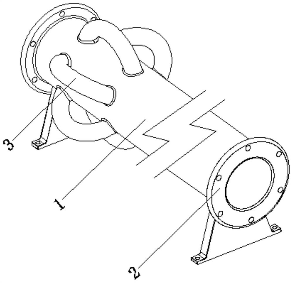
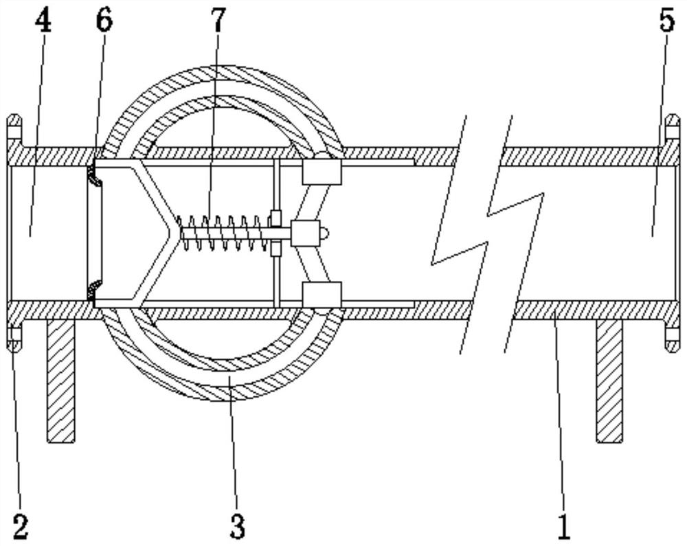
[0029] see Figure 1-5 , the present invention provides a technical solution: a municipal sewage pipeline, comprising a main pipe 1, a connecting flange 2, and a branch pipe 3, the connecting flange 2 is arranged at the end of the main pipe 1, and the branch pipe 3 is fixed and communicated with the main pipe the surface of the tube 1 and close to the end position;
[0030] The interior of the main flow pipe 1 is provided with an inlet 4, an outlet 5, a horn deflector 6, and an anti-reflux device 7. The inlet 4 is arranged at the end of the main flow 1 and is close to the position of the branch pipe 3, and the outflow The port 5 is set at the end of the main flow pipe 1 away from the inlet 4, the horn deflector 6 is fixed inside the main flow pipe 1 and located at the position of the inlet 4, and the anti-backflow device 7 is arranged inside the main flow pipe 1 and close to the horn The position of the deflector 6 and the matching connection with the branch pipe 3 can effect...
Embodiment example 2
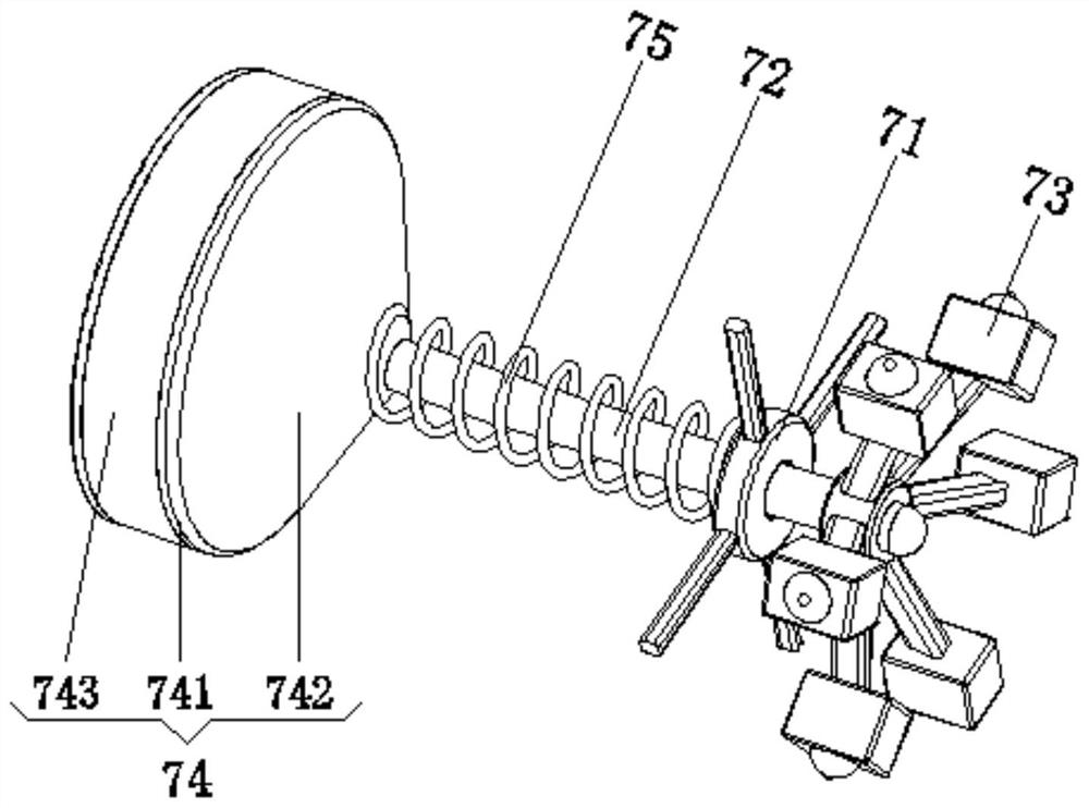
[0032] The anti-backflow device 7 is provided with a support frame 71, a guide rod 72, a clamping device 73, a flow conversion device 74, and a return spring 75. Sliding connection at the inner central position of the guide rod 73, the clamping device 73 is arranged at the end of the guide rod 72, the flow converter 74 is arranged at the end of the guide rod 72 away from the clamping device 73, and the return spring 75 is fixed on the surface of the support frame 71 and the converter Between the two sides corresponding to the surface of the device 74 and on the surface of the guide rod 72, when the fluid enters from the inlet 4, under the action of pressure, the guide rod 72 can slide on the support frame 71. At this time, the fluid The pressure will change the flow device 74 to move to the right, so that the fluid enters the branch pipe 3, changing the whereabouts of the fluid, and the return spring 75 is compressed, and then returns to the main pipe 1, so that the sewage can ...
Embodiment example 3
[0034]The clamping device 73 is provided with a base block 731, a ball slide block 732, an arc elastic member 733, a ball 734, and a gasket 735. One end of the base block 731 is fixedly connected with the surface end of the guide rod 72, and the ball slide block 732 Slidingly connected to the inside of the base block 731 and away from the end of the guide rod 72, the arc-shaped elastic member 733 is arranged inside the base block 731 and at the bottom of the ball slider 732, and the ball 734 is arranged at the top center of the ball slider 732 position, the gasket 735 is set on the top surface of the ball slider 732 and close to the position of the ball 734, when the flow converter 74 is subjected to fluid pressure, as the guide rod 72 slides on the guide rod 72, it will drive the base block 731 to slide , so that the ball head slider 732 cooperates with the port of the branch pipe 3 under the elastic force of the arc-shaped elastic member 733, so that the opening and closing o...
PUM
 Abstract
Description
Claims
Application Information
 - R&D
- Intellectual Property
- Life Sciences
- Materials
- Tech Scout
- Unparalleled Data Quality
- Higher Quality Content
- 60% Fewer Hallucinations
Browse by: Latest US Patents, China's latest patents, Technical Efficacy Thesaurus, Application Domain, Technology Topic, Popular Technical Reports.
© 2025 PatSnap. All rights reserved.Legal|Privacy policy|Modern Slavery Act Transparency Statement|Sitemap|About US| Contact US: help@patsnap.com


