Ultrasonic co-frequency observation device and method for directly displaying second modal waves

A technology of observation device and detection device, which is applied in the direction of measuring device, machine/structural component testing, aircraft component testing, etc., and can solve the problems of high price, limited spatial resolution, inability to realize direct measurement and display of the second modal wave, etc. , to achieve the effect of simple installation

Pending Publication Date: 2022-02-18
NANJING UNIV OF AERONAUTICS & ASTRONAUTICS
View PDF25 Cites 0 Cited by
  • Summary
  • Abstract
  • Description
  • Claims
  • Application Information

AI Technical Summary

Problems solved by technology

[0003] The thickness of the hypersonic boundary layer is thin, the velocity gradient in the boundary layer is relatively large, and the frequency of the second mode wave is very high, usually on the order of hundreds of kilohertz. On the one hand, it can capture the change information of the flow density gradient caused by the second mode wave, but the test equipment is expensive, the optical path layout and adjustment are more complicated, and only the relatively large density gradient change caused by the disturbance development in the boundary layer can be obtained, which cannot be realized. The direct measurement of the second mode wave shows that it is impossible to accurately obtain the acoustic characteristics such as the propagation and reflection of the second mode wave in the boundary layer.
[0004] Another method by arranging high-frequency pressure sensors on the wall can only obtain single-point wall pulsation pressure information, and cannot obtain the spatial propagation characteristics of the second mode wave
If you want to obtain the flow direction development information of the second mode wave, you need to arrange multiple high-frequency pressure sensors on the wall of the model. The high-frequency pressure sensors are not only expensive, but also have high installation requirements. It is necessary to ensure that the surface of the sensor is installed flush with the wall of the model. to minimize disruption to the flow
Moreover, the minimum diameter of the high-frequency pressure sensor is more than three millimeters, which is larger than the wavelength of the second mode wave, which limits the spatial resolution of the sensor measurement, and its accuracy for measuring the second mode wave cannot be guaranteed.

Method used


Image

  • Ultrasonic co-frequency observation device and method for directly displaying second modal waves
  • Ultrasonic co-frequency observation device and method for directly displaying second modal waves

Examples


Embodiment Construction

[0023] The following will clearly and completely describe the technical solutions in the embodiments of the present invention with reference to the accompanying drawings in the embodiments of the present invention. Obviously, the described embodiments are only some, not all, embodiments of the present invention. Based on the embodiments of the present invention, all other embodiments obtained by persons of ordinary skill in the art without making creative efforts belong to the protection scope of the present invention.

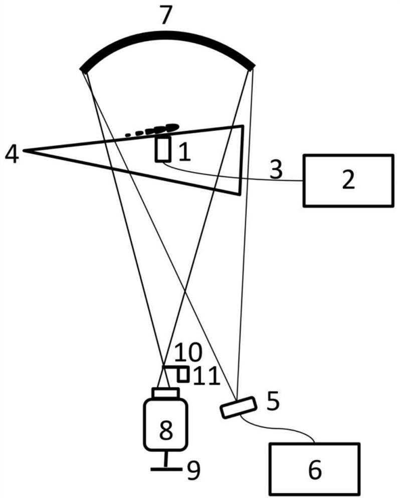
[0024] The invention discloses an ultrasonic co-frequency observation device for direct display of the second mode, which is mainly aimed at the observation of the second mode wave in the hypersonic boundary layer, adopts an ultrasonic co-frequency LED light source, and uses a signal generator to control the LED The frequency of the light source makes it differ from the frequency of the second modal wave by a few hertz, and the spatial distribution of the secon...


PUM


Abstract

The invention discloses an ultrasonic co-frequency observation device and method for directly displaying a second modal wave. The ultrasonic co-frequency observation device comprises a second modal wave detection device, an ultrasonic co-frequency optical path system and an image acquisition system, the second modal wave detection device is used for detecting a pressure signal of the second modal wave; the ultrasonic same-frequency light path system is used for providing a light source for the display of the second modal wave, emitting a light beam matched with the frequency of the pressure signal, and focusing the light beam to form an image of a point light source; and the image acquisition system is used for shooting and recording the image.

Description

technical field [0001] The invention relates to the technical field of hypersonic boundary layer flow observation and measurement, in particular to an ultrasonic co-frequency observation device and method for direct display of a second modal wave. Background technique [0002] The hypersonic boundary layer transition has an important impact on the aerothermal and aerodynamic forces of the aircraft, and the second mode wave is dominant in the hypersonic boundary layer transition. At present, two methods are mainly used to observe the acoustic mode of the second mode wave. One is the observation method of space field based on optics, such as schlieren, shadow and flow display based on Rayleigh scattering, and the schlieren method is a function based on the density gradient, the shadow method is based on the second derivative of the density gradient, and the Rayleigh scattering flow display method is based on the intensity of light reflected by tiny particles in the flow to dis...

Claims


Application Information

Patent Timeline
Patent Type & Authority Applications(China)
IPC IPC(8): G01M9/02G01M9/06B64F5/60
CPCG01M9/02G01M9/06B64F5/60
Inventor 张传鸿任宗盛史志伟
Owner NANJING UNIV OF AERONAUTICS & ASTRONAUTICS
Why Eureka
Try Eureka