
Cigarette making machine forming constant-temperature equipment

A technology of constant temperature equipment and cigarette making machines, which is applied in the fields of tobacco, temperature control, and cigarette manufacturing, and can solve problems such as difficult cleaning, easy accumulation of dust, and affecting cooling efficiency of fans

Pending Publication Date: 2022-02-18
宁波市永旭机电设备有限公司
View PDF0 Cites 0 Cited by
  • Summary
  • Abstract
  • Description
  • Claims
  • Application Information

AI Technical Summary

Problems solved by technology

[0004] The purpose of the present invention is to solve the shortcomings in the prior art that when the traditional constant temperature equipment is used for a long time, the surface of the wind cover of the fan tends to accumulate more dust, is difficult to clean, and easily affects the cooling efficiency of the fan, and proposes a cigarette making machine Forming constant temperature equipment

Method used


Image

  • Cigarette making machine forming constant-temperature equipment
  • Cigarette making machine forming constant-temperature equipment
  • Cigarette making machine forming constant-temperature equipment

Examples


Embodiment 1

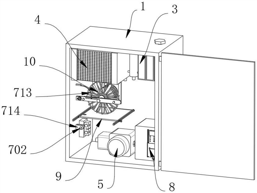
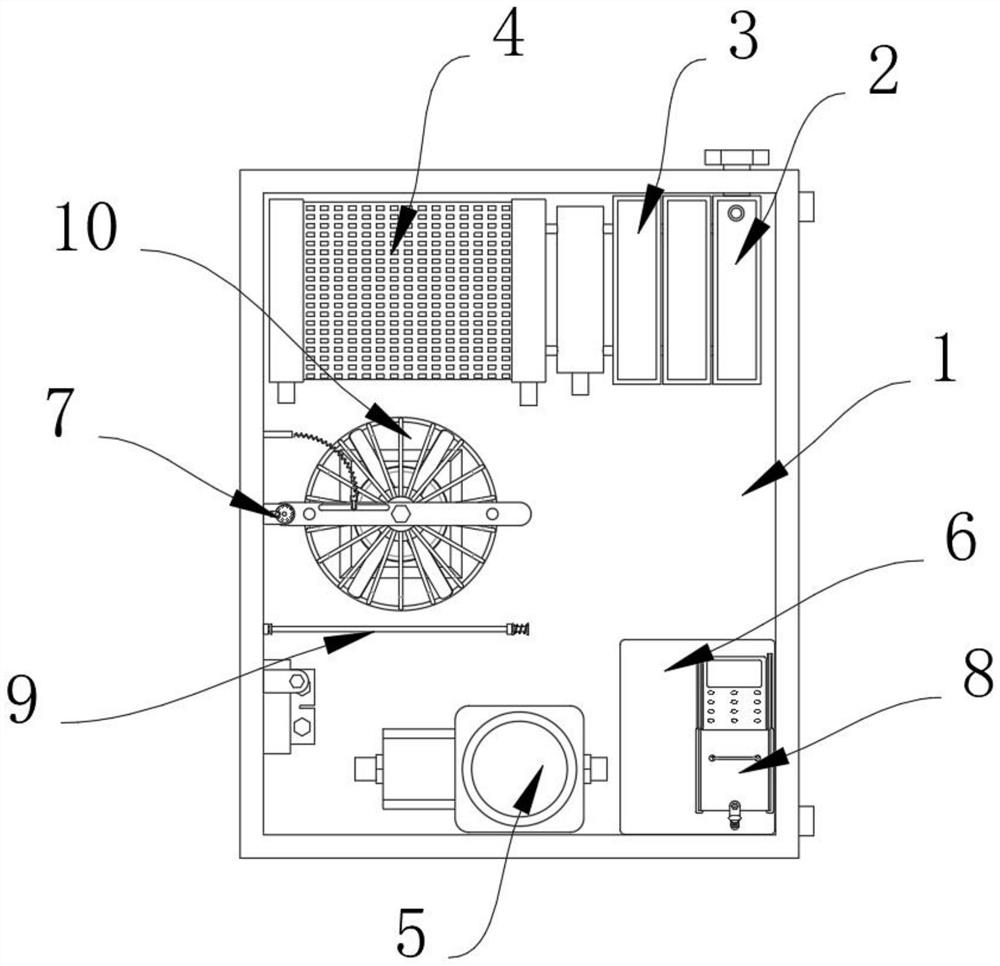
[0031] Example 1, such as Figure 1-8As shown, the present invention provides a cigarette machine forming constant temperature equipment, including a casing 1, a cooling block 2 is installed inside the casing 1, two cooling blocks 3 are installed on one side of the cooling block 2, and the cooling blocks 3 are far away from the cooling A radiator 4 is installed on one side of the block 2, a pump body 5 is installed inside the casing 1, a control electrical box 6 is installed inside the casing 1, a fan 10 is installed on the rear inner wall of the casing 1, and a fan 10 is installed on the inner wall of the casing 1. The inner wall is provided with a cleaning structure 7 , the surface of the control electrical box 6 is provided with a protective structure 8 , and the inner wall of the casing 1 is provided with a collecting structure 9 .

[0032] Let's talk about the specific settings and effects of its cleaning structure 7, protective structure 8 and collection structure 9 belo...

Embodiment 2

[0039] Embodiment 2, on the basis of Embodiment 1, the collection structure 9 includes a rotating shaft 91, the rotating shaft 91 is rotatably connected to the inner wall of the casing 1, the arc surface of the rotating shaft 91 is fixedly connected with a collecting cloth 92, and the surface of the collecting cloth 92 is provided with A hole 96 is reserved, and the end of the collecting cloth 92 away from the rotating shaft 91 is fixedly connected with a fixed rod 93, and one end of the fixed rod 93 is fixedly connected with a limit block 94, and the arc surface of the limit block 94 is slidably connected with a limit rail 95, and the limit rail 95 is fixedly connected to the inner wall of the casing 1, and the arc surface of the fixed rod 93 is slidably connected with a fixed rail 97, and one end of the fixed rail 97 is fixedly connected with the casing 1, so that when the cleaning structure 7 is used to clean the blower fan 10, The effect of collecting the dust under the sur...


PUM


Abstract

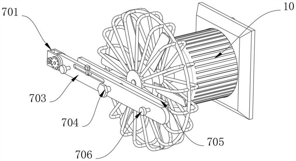
The invention provides cigarette making machine forming constant-temperature equipment, and relates to the technical field of cigarette making machines. The equipment comprises a machine shell, a cooling block is installed in the machine shell, two heat dissipation blocks are installed on one side of the cooling block, a heat dissipation device is installed on the side, away from the cooling block, of each heat dissipation block, a pump body is installed in the machine shell, a control electric appliance box is installed in the machine shell, a fan is installed on the inner wall of the rear side of the machine shell, a cleaning structure is arranged on the inner wall of the machine shell and comprises a fixing frame, the fixing frame is fixedly connected to the inner wall of the machine shell, the inner wall of the fixing frame is rotationally connected with a rotating plate, a screw rod is inserted into the rotating plate in a threaded mode, and the end, close to the draught fan, of the screw is rotationally connected with a cleaning pad. The problems that when traditional constant-temperature equipment is used for a long time, much dust is likely to accumulate on the surface of a fan cover of a fan, cleaning is not easy, and the cooling efficiency of the fan is likely to be affected are solved.

Description

technical field [0001] The invention relates to the technical field of cigarette making machines, in particular to a forming constant temperature equipment for a cigarette making machine. Background technique [0002] Cigarette rolling machine is a machine that rolls shredded tobacco into cigarettes with cigarette paper. It is the main cigarette machine and is usually produced in an assembly line. With the development of the times, the functions of cigarette rolling machines have gradually been improved, and it is widely used in the field of cigarette production. [0003] The constant temperature equipment of the cigarette machine is a kind of cigarette machine. In order to cool down the equipment in the constant temperature equipment of the cigarette machine, a fan is installed in the constant temperature equipment for air cooling. When the traditional constant temperature equipment is used for a long time, the surface of the wind cover of the fan is easy. A lot of dust is ...

Claims


Application Information

Patent Timeline
Patent Type & Authority Applications(China)
IPC IPC(8): G05D23/19A24C5/00
CPCG05D23/1931A24C5/00
Inventor 鲁旭君
Owner 宁波市永旭机电设备有限公司
Learn More