Multi-efficient heat dissipation system for battery of electric automobile

A technology for electric vehicles and heat dissipation systems, applied in secondary batteries, circuits, electrical components, etc., can solve problems such as limited space for battery installation, impact on performance and service life, and rise in temperature at the location of the battery, so as to improve the heat dissipation effect and volume Small, good cooling effect

Inactive Publication Date: 2022-02-18
ZHEJIANG IND POLYTECHNIC COLLEGE
View PDF0 Cites 3 Cited by
  • Summary
  • Abstract
  • Description
  • Claims
  • Application Information

AI Technical Summary

Problems solved by technology

[0003] The battery is the core component of an electric vehicle, and its performance directly affects the quality of the vehicle. The battery of an electric vehicle is generally composed of multiple cells connected in series. When the electric vehicle is running, each cell will The phenomenon of heating occurs. If the heat dissipation cannot be carried out well, the heat generated by each cell will cause the temperature of the battery to rise sharply, which will cause the battery to heat up. The battery will work under the condition of overheating for a long time, which will reduce its performance and service life. In severe cases, serious accidents such as explosions or fires may occur
[0004] In the prior art, heat dissipation and cooling are generally carried out by air cooling or liquid cooling. In order to improve the effect of heat dissipation, it is usually necessary to use power equipment to drive the flow of air and coolant. Because the air and coolant need to be driven by different power equipment, and the battery The installation space is limited. In order to save space or reduce costs, the heat dissipation of batteries in the prior art can only be air-cooled or liquid-cooled, which often has the disadvantages of single heat dissipation means and poor heat dissipation effect.

Method used


Image

  • Multi-efficient heat dissipation system for battery of electric automobile
  • Multi-efficient heat dissipation system for battery of electric automobile
  • Multi-efficient heat dissipation system for battery of electric automobile

Examples


Embodiment 1

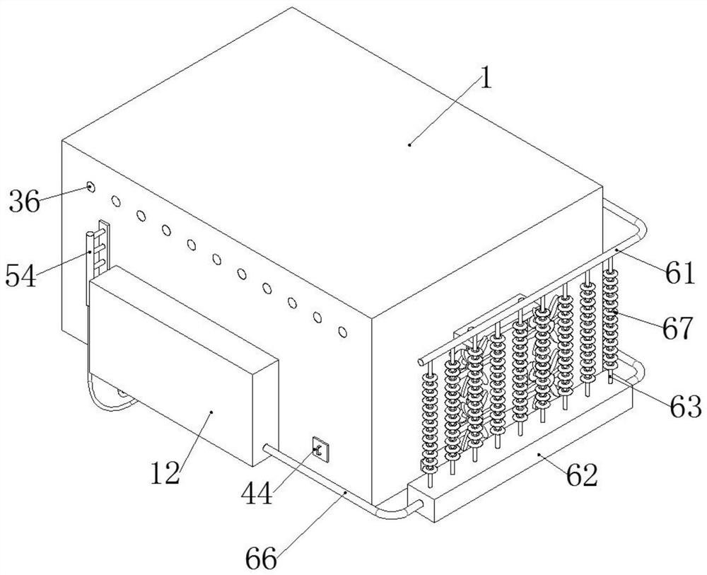
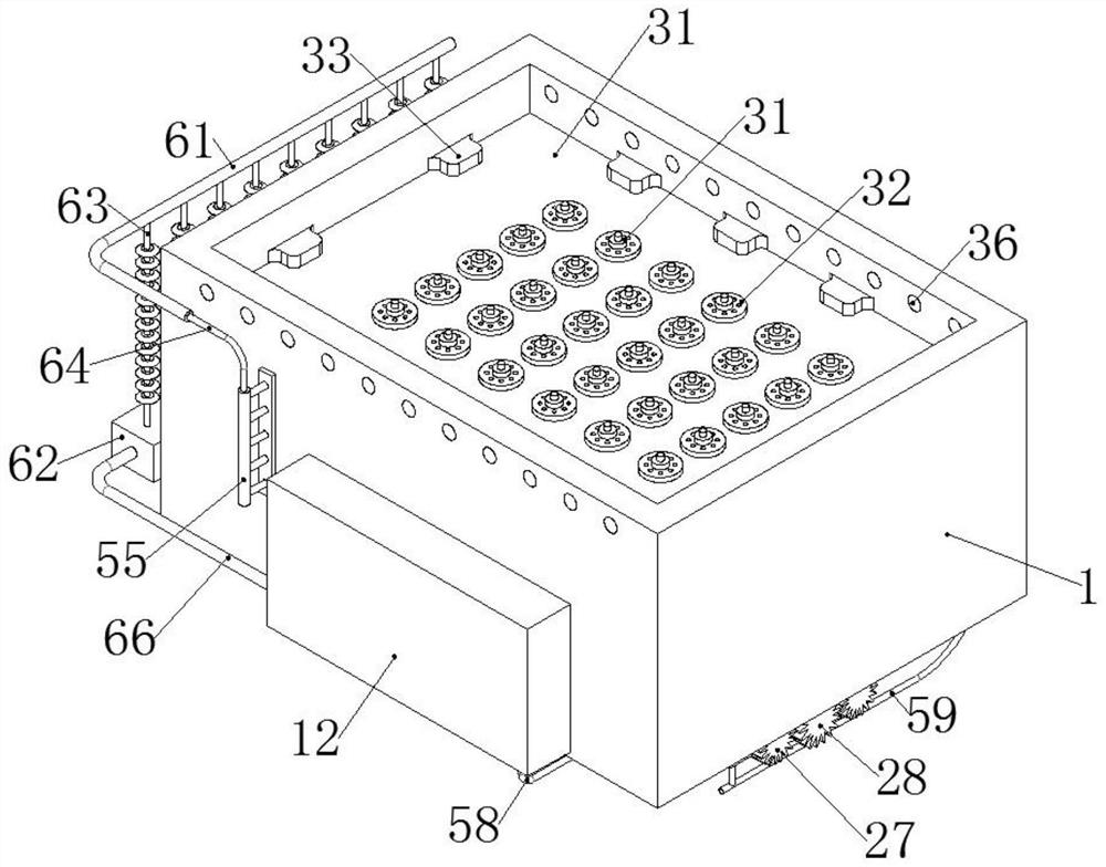
[0048] A multiple high-efficiency heat dissipation system for batteries of electric vehicles, including an installation case 1 and a battery cell 11 arranged in the installation case 1, the outer walls of the front and rear side panels of the installation case 1 are symmetrically fixed with a cooling box 12, and also includes a pump Sending device, air cooling device, filter device 4, liquid cooling device and cooling device;

[0049] The pumping device is located at the bottom of the installation shell 1;

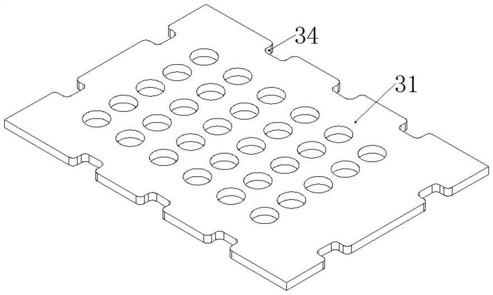
[0050] The air-cooling device includes a bracket 31 and a cooling fan 32; the bracket 31 is fixedly connected in the installation housing 1 and a pair is arranged at intervals up and down, the inner wall of the installation housing 1 is fixedly connected with a welding seat 33, and the bracket 31 is provided with The notch 34 corresponding to the welding seat 33, the notch 34 and the welding seat 33 are fixed by welding, the cooling fan 32 is fixed between the brackets 31,...

Embodiment 2

[0061] On the basis of Embodiment 1, this embodiment discloses the following specific structure of the pumping device:

[0062] The pumping device includes a pump chamber 21, a reciprocating screw rod 22, a piston 23 and a motor 24; the pump chamber 21 is fixedly connected to the bottom of the installation housing 1 and arranged symmetrically front and back, and the reciprocating screw rod 22 passes through the first shaft rod 25 and the The second shaft rod 26 is rotatably connected in the pump chamber 21, the head of each first shaft rod 25 stretches out of the pump chamber 21 and is fixedly connected with a driven gear 27, and the piston 23 is sealingly and slidingly connected in the pump chamber 21 and The reciprocating screw mandrel 22 meshes, and the motor 24 is fixedly connected between the pump chambers 21. The output shaft head of the motor 24 is fixedly connected with a driving gear 28, and two driven gears 27 mesh with it at the front and rear sides of the driving ge...

Embodiment 3

[0067] On the basis of Embodiment 2, this embodiment discloses the connection structure between the air cooling device and the pump chamber 21, and specifically discloses the following technical features:

[0068] The right side of each pump chamber 21 is fixedly connected with a one-way air inlet pipe 37, and the right side of the bottom plate of each pump chamber 21 is fixedly connected with a one-way air outlet pipe 38. The direction that the one-way air outlet pipe 38 allows gas to pass is the direction away from the inner cavity of the pump chamber 21, and the one-way air inlet pipe 37 and the one-way air outlet pipe 38 realize the one-way conduction ability through the one-way air valve provided therein, forming The bottom of a group of heat dissipation air cylinders 32 in the row is connected with a first pipe 39, the right end of each first pipe 39 is connected with the filter device 4, and the filter device 4 is also connected with a second pipe 310, and the second pip...


PUM


Abstract

The invention discloses a multiple efficient heat dissipation system for a battery of an electric automobile. The multiple efficient heat dissipation system comprises a mounting shell and a battery cell arranged in the mounting shell, wherein cooling boxes are symmetrically and fixedly connected to outer walls of a front side plate and a rear side plate of the mounting shell, the multiple efficient heat dissipation system further comprises a pumping device, an air cooling device, a filtering device, a liquid cooling device and a cooling device, and the air cooling device comprises a bracket and a heat dissipation air duct. The system is advantaged in that the pumping device serves as a power source, external fresh air enters the cooling air duct to achieve air cooling heat dissipation, liquid cooling heat dissipation is achieved through flowing of cooling liquid, double heat dissipation is combined, the heat dissipation effect is improved, the pumping device provides power for flowing of the cooling liquid and the fresh air at the same time, the size of the device is smaller, compared with a traditional battery with a single heat dissipation mode, the installation size of the system is not greatly increased, and manufacturing cost of the heat dissipation system is not excessively increased.

Description

technical field [0001] The invention relates to the technical field of battery auxiliary systems for electric vehicles, in particular to a multiple high-efficiency cooling system for batteries of electric vehicles. Background technique [0002] Electric vehicles use electricity as the main power source or auxiliary power source, and integrate advanced technologies in vehicle power control and drive to form vehicles with advanced technical principles, new technologies, and new structures. [0003] The battery is the core component of an electric vehicle, and its performance directly affects the quality of the vehicle. The battery of an electric vehicle is generally composed of multiple cells connected in series. When the electric vehicle is running, each cell will The phenomenon of heating occurs. If the heat dissipation cannot be carried out well, the heat generated by each cell will cause the temperature of the battery to rise sharply, which will cause the battery to heat u...

Claims


Application Information

Patent Timeline
Patent Type & Authority Applications(China)
IPC IPC(8): H01M10/613H01M10/625H01M10/643H01M10/6563H01M10/6566H01M10/6568H01M10/6551
CPCH01M10/613H01M10/625H01M10/643H01M10/6563H01M10/6566H01M10/6568H01M10/6551Y02E60/10
Inventor 丁奇朱洪军戴俊豪冯军刘腾达
Owner ZHEJIANG IND POLYTECHNIC COLLEGE
Why Eureka
Try Eureka