
Device for driving engine charging by automobile exhaust

A technology of automobile exhaust and generator, applied in the direction of exhaust device, engine, wind power generation, etc., can solve the problems of wind turbine load increase, high cost, affecting the service life of wind turbine, etc., and achieve the effect of reducing load

Inactive Publication Date: 2018-06-01
ZHENGZHOU GUANGZHIYUAN ELECTRONICS TECH CO LTD
View PDF0 Cites 2 Cited by
  • Summary
  • Abstract
  • Description
  • Claims
  • Application Information

AI Technical Summary

Problems solved by technology

[0002] At present, with the continuous development of society, there are more and more cars. Because the exhaust pipes of cars will emit a lot of waste gas, it will cause a lot of pollution. The treatment and reuse of various exhaust gases have been put on the agenda. There are two main energy sources that can be used by automobile exhaust, one is thermal energy and the other is wind energy. Since the heat exchange generator is extremely complex and the pipeline is small, if the energy in the pipeline is The cost of setting up a heat exchange generator is extremely high. When the existing exhaust gas is used for wind power generation, because the dust particles in the exhaust gas gather on the blades of the wind turbine for a long time and are cleaned irregularly, the resistance will increase and the wind turbine will be damaged. The load increases, because the wind turbine works for a long time and does not dissipate heat in time, it will affect the service life of the wind turbine

Method used


Image

  • Device for driving engine charging by automobile exhaust
  • Device for driving engine charging by automobile exhaust
  • Device for driving engine charging by automobile exhaust

Examples


Embodiment Construction

[0020] In order to make the technical means, creative features, goals and effects achieved by the present invention easy to understand, the present invention will be further described below in conjunction with specific embodiments.

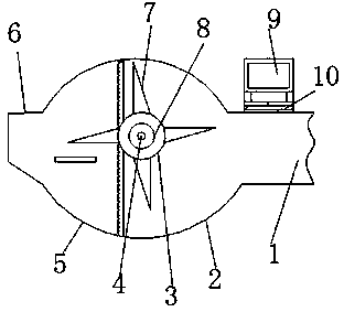
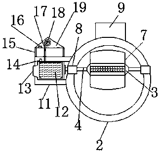
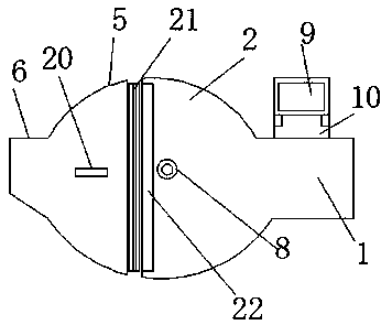
[0021] Such as Figure 1-5 As shown, a device for charging a generator driven by automobile exhaust gas, including a first cavity 2 and a second cavity 5, the right end of the first cavity 2 is connected to an air intake pipe 1 in a horizontal direction, and the top of the air intake pipe 1 A heat insulation board 10 is installed horizontally, and a battery 9 is installed vertically on the top of the heat insulation board 10. The position of the upper middle part of the left and right sides of the second cavity 5 is symmetrical and a sealed bearing 8 is installed horizontally. The second cavity 5. A chassis 11 is installed vertically in the middle of the left end, and a wind generator 12 is installed horizontally inside the chassis 11. The left an...


PUM


Abstract

The invention discloses a device for driving engine charging by automobile exhaust. The device comprises a first cavity and a second cavity, the right end of the first cavity is horizontally connectedwith an air inlet pipe, an insulation board is horizontally mounted at the top of the air inlet pipe, a storage battery is vertically mounted at the top of the insulation board, and sealing bearingsare symmetrically and horizontally mounted at middle upper positions of the left side and the right side of the second cavity. A temperature sensor is mounted at the left end of the top of the inner wall of a case, a processor is mounted at the left end of the inner wall of an air blower mounting box, and an air blower is vertically mounted inside the air blower mounting box. When heat generated in long-time operation of a wind driven generator is higher than a temperature set value of the temperature sensor, the temperature sensor transmits data to the processor, the processor transmits signals to the air blower, air blown by the air blower facilitates cooling of the wind driven generator in the case, and the device is practical and suitable for wide popularization and use.

Description

technical field [0001] The invention relates to a charging device, in particular to a device for charging a generator driven by automobile exhaust. Background technique [0002] At present, with the continuous development of society, there are more and more cars. Because the exhaust pipes of cars will emit a lot of waste gas, it will cause a lot of pollution. The treatment and reuse of various exhaust gases have been put on the agenda. There are two main energy sources that can be used by automobile exhaust, one is thermal energy and the other is wind energy. Since the heat exchange generator is extremely complex and the pipeline is small, if the energy in the pipeline is The cost of setting up a heat exchange generator is extremely high. When the existing exhaust gas is used for wind power generation, because the dust particles in the exhaust gas gather on the blades of the wind turbine for a long time and are cleaned irregularly, the resistance will increase and the wind t...

Claims


Application Information

Patent Timeline
Patent Type & Authority Applications(China)
IPC IPC(8): F01N5/04F01N13/14F03D9/11F03D80/55F03D80/60F04D27/00
CPCF01N5/04F01N13/14F04D27/008F03D9/11F03D80/55F03D80/60Y02E10/72Y02E70/30Y02T10/12
Inventor 史东生
Owner ZHENGZHOU GUANGZHIYUAN ELECTRONICS TECH CO LTD
Learn More