


Quick Research
Generate reliable direction feasibility study reports for your R&D in just a few steps.

Technical Q&A
Discover and master advanced knowledge NOW. Basics, ideas, possibilities, all at once.

Find Solutions
As an expert in R&D theories, this can generate solutions to your technical problems instantly.

Evaluate Feasibility
Analyze your overall solution with one click, know your potential R&D risks in advance.

Monitor Landscape
Get weekly tech updates, stay abreast of the latest tech innovations and key insights.
Relay protection circuit and method, battery management system and electric vehicle
A technology for relay protection and protection circuits, which is applied in emergency protection circuit devices, electric vehicles, battery/fuel cell control devices, etc. It can solve problems such as potential safety hazards, sticking of power relay contacts, and difficult detection of relay jitter states, so as to prevent The effect of contact sticking
- Summary
- Abstract
- Description
- Claims
- Application Information
AI Technical Summary
Problems solved by technology
Method used
Image

Examples
Embodiment 1
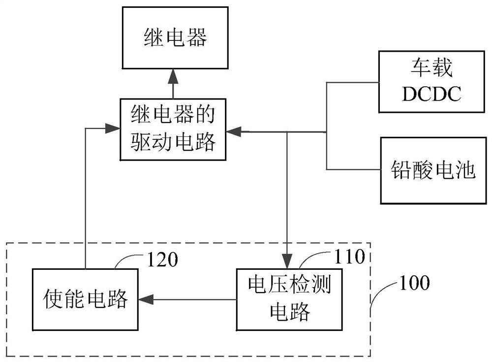
[0035] Embodiment 1 of the present application provides a relay protection circuit. The structure diagram of the relay protection circuit includes an enabling circuit and a voltage detection circuit. The input end of the voltage detection circuit is electrically connected to the first end of the drive circuit of the relay; the output of the voltage detection circuit When the voltage detection circuit detects that the power supply voltage of the drive circuit is lower than the pull-in voltage of the relay, it will send a work instruction to the enable circuit; the output end of the enable circuit is connected to the first drive circuit. The two terminals are electrically connected, and the enabling circuit outputs a control signal according to the work instruction, so that the driving circuit controls the relay to be disconnected according to the control signal.
[0036] optional, figure 1 A structural diagram of a relay protection circuit provided for the embodiment of the pre...
Embodiment 2
[0045] The embodiment of the present application provides a relay protection method, such as Figure 5 as shown, Figure 5 A relay protection method provided in an embodiment of the present application, the relay protection method includes the following steps;
[0046] Step 101, detecting the power supply voltage of the driving circuit of the relay.
[0047] Among them, the drive circuit is used to control the closing or opening of the relay. For example, the power supply voltage of the drive circuit can be derived from the vehicle-mounted DCDC and / or lead-acid battery (12V), and the vehicle-mounted DCDC and / or lead-acid battery (12V) not only supplies power to the drive circuit of the relay, but also supplies power to multiple electrical appliances at the same time , when it is affected by other electrical appliances, it will cause a large drop in voltage, so it is prone to abnormal fluctuations in the voltage of the power supply. The contacts of the relay vibrated, and re...
Embodiment 3
[0063] Based on the relay protection circuit described in the first embodiment above, the embodiment of the present application provides a battery management system, the battery management system (Battery Management System, referred to as BMS) includes but not limited to a control unit, a relay drive circuit, a relay protection circuit , the power supply for the relay drive circuit can be from the vehicle backup lead-acid battery (12V) and / or vehicle DCDC power supply, BMS is an important system for controlling power batteries on electric vehicles, for example, BMS is used to control but not limited to battery packs High voltage power on and off, battery pack SOX state, etc., where SOX state includes but not limited to SOC, SOP estimation, SOC is used to indicate the state of charge estimation of the power lithium battery, reflecting the safety and capacity decay of the lithium battery pack, battery SOP Estimates are used to indicate battery power status, usually expressed as s...
PUM
 Abstract
Description
Claims
Application Information
 - R&D Engineer
- R&D Manager
- IP Professional
- Industry Leading Data Capabilities
- Powerful AI technology
- Patent DNA Extraction
Browse by: Latest US Patents, China's latest patents, Technical Efficacy Thesaurus, Application Domain, Technology Topic, Popular Technical Reports.
© 2024 PatSnap. All rights reserved.Legal|Privacy policy|Modern Slavery Act Transparency Statement|Sitemap|About US| Contact US: help@patsnap.com