Ultrasonic piezoelectric motor, camera module and electronic equipment

A piezoelectric motor, ultrasonic technology, applied in the field of photography

Active Publication Date: 2022-02-22
HUAWEI TECH CO LTD
View PDF13 Cites 2 Cited by
  • Summary
  • Abstract
  • Description
  • Claims
  • Application Information

AI Technical Summary

Problems solved by technology

Ultrasonic piezoelectric motor adopts piezoelectric drive technology, which solves the electromagnetic interference problem o

Method used


Image

  • Ultrasonic piezoelectric motor, camera module and electronic equipment
  • Ultrasonic piezoelectric motor, camera module and electronic equipment
  • Ultrasonic piezoelectric motor, camera module and electronic equipment

Examples


Embodiment Construction

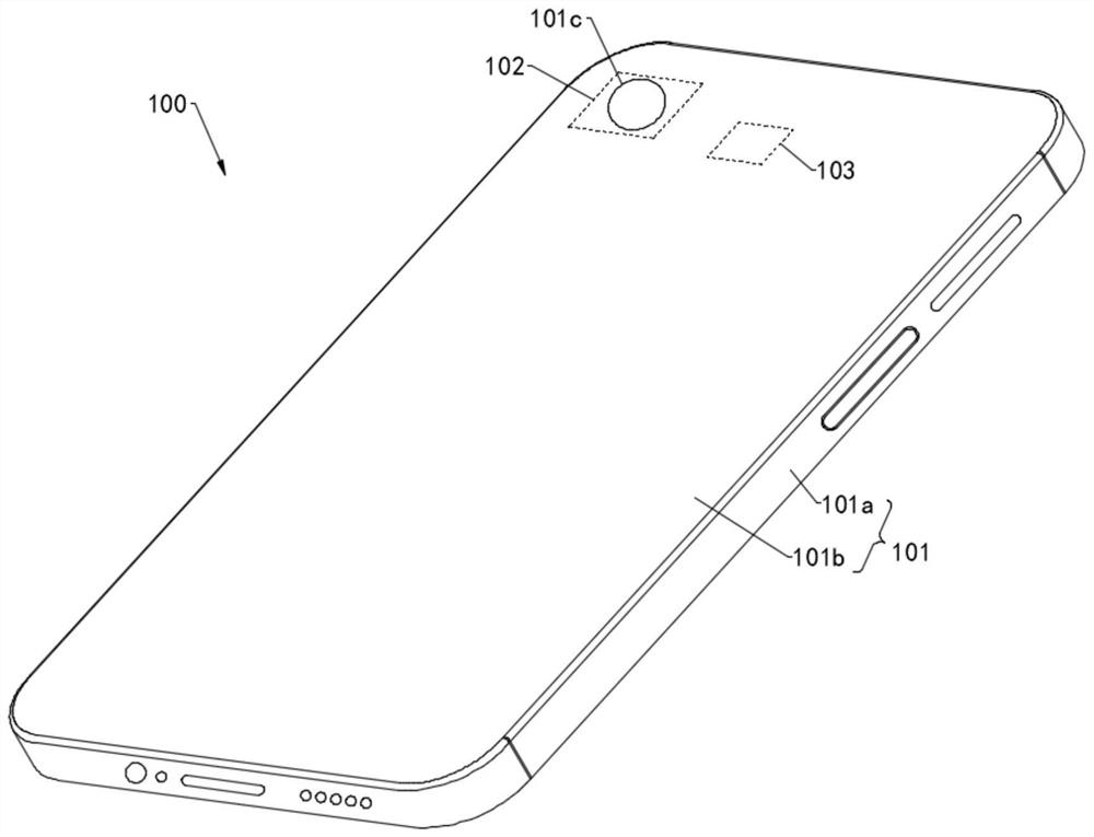
[0122] The technical solutions in the embodiments of the present application will be described below with reference to the accompanying drawings.

[0123] Among them, in the description of the embodiments of the present application, unless otherwise specified, the "and / or" in the text is only an association relationship describing the associated object, indicating that there may be three relationships, for example, A and / or B, It can mean: A exists alone, A and B exist simultaneously, and B exists alone. In addition, in the description of the embodiments of the present application, "multiple" means two or more than two.

[0124] The orientation terms mentioned in the embodiments of the present application, for example, "upper", "lower", "front", "rear", "left", "right", "inner", "outer", "side", "Top", "bottom" and so on are only referring to the directions of the drawings. Therefore, the orientation terms used are for better and clearer description and understanding of the em...


PUM


Abstract

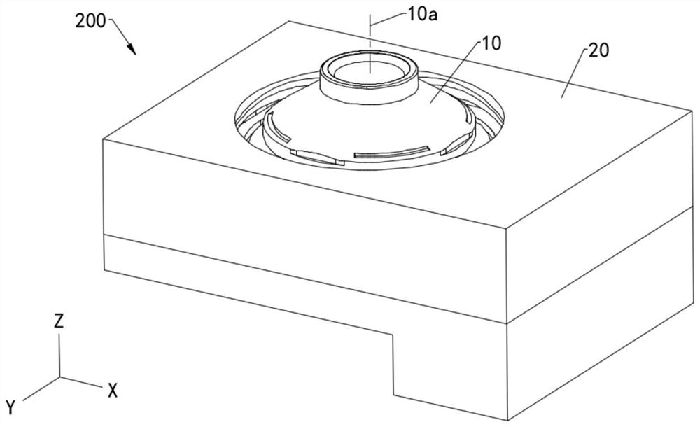
The invention discloses an ultrasonic piezoelectric motor, a camera module and electronic equipment. The ultrasonic piezoelectric motor comprises a support, a carrier and a Z-direction piezoelectric actuator, the carrier is installed on the inner side of the support and can move in the Z direction relative to the support, the carrier is used for installing a lens, and the Z direction is parallel to the optical axis of the lens; the Z-direction piezoelectric actuator is located between the support and the carrier, the Z-direction piezoelectric actuator comprises a Z-direction base block, a Z-direction extension block and a Z-direction contact block which are stacked, the Z-direction base block is fixed to the support, the Z-direction base block is used for deforming according to a first electric signal to drive the Z-direction contact block to abut against or leave the carrier, and the Z-direction extension block is used for deforming according to a second electric signal to drive the Z-direction contact block to move along the Z direction. The ultrasonic piezoelectric motor periodically abuts against the carrier through the Z-direction contact block of the Z-direction piezoelectric actuator and drives the carrier to move in the Z direction so that automatic focusing of the camera module is achieved.

Description

technical field [0001] The present application relates to the technical field of photographing, and in particular to an ultrasonic piezoelectric motor, a camera module and electronic equipment. Background technique [0002] At present, the motors of the camera modules of electronic devices (such as mobile phones) are mainly moving coil motors. The moving coil motor includes a magnet and a coil. The coil is wound on the outer peripheral side of the lens. Under the magnetic field of the magnet, the energized coil generates electromagnetic force, thereby pushing the lens to move and realizing auto focus (AF) of the camera module. However, since the moving coil motor is driven by magnetic force, it is sensitive to surrounding magnetic materials or magnetic fields, and is prone to magnetic interference, resulting in insufficient focus or anti-shake accuracy, resulting in poor shooting quality of the camera module. Contents of the invention [0003] The purpose of this applicat...

Claims


Application Information

Patent Timeline
IPC IPC(8): G02B7/09G02B27/64G03B5/00G03B30/00
CPCG02B7/09G02B27/646G03B5/00G03B30/00G02B7/08G03B2205/0061G03B3/10G02B13/007G02B26/0816G03B2205/0038H02N2/026H02N2/028H02N2/0025H02N2/103G02B7/28G03B5/04G03B13/36G03B2205/0015H02N2/067
Inventor 李邓峰何瑛勇边心秀丁肇元
Owner HUAWEI TECH CO LTD
Why Eureka
Try Eureka