Lighting equipment

A technology for lighting equipment and lighting areas, which is applied in the field of visual inspection or scanning systems, and can solve problems such as unfavorable imaging and inspection operations, and uniform distribution of illumination light

Pending Publication Date: 2022-02-22
J TECH MATERIAL
View PDF0 Cites 0 Cited by
  • Summary
  • Abstract
  • Description
  • Claims
  • Application Information

AI Technical Summary

Problems solved by technology

Although this lighting method can increase the light-receiving angle of the inspected area, it is still not enough to evenly distribute the illumination light in the range of 360 degrees. It may appear that the reflected light intensity is greater than that of tiny dust or foreign objects at a specific angle, so it is not conducive to image acquisition and inspection operations

Method used


Image

  • Lighting equipment
  • Lighting equipment
  • Lighting equipment

Examples


Embodiment Construction

[0052] Hereinafter, corresponding preferred embodiments are listed in conjunction with each figure to describe the constituent components and the achieved effects of the lighting device of the present invention. However, the components, sizes, appearances, and lighting ranges of the lighting equipment in each drawing are only used to illustrate the technical features of the present invention, but not to limit the present invention.

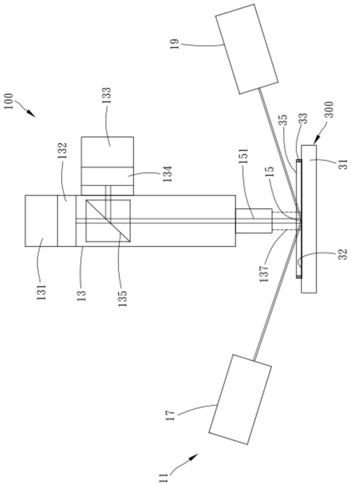
[0053] like figure 1 As shown, the lighting device of the present invention is often applied in a visual scanning system 100 of a specific process. The visual scanning system 100 takes a partial image of the inspected surface of the inspected object and uses known image processing techniques to inspect the image and map the inspected surface. state, and mark information on the inspected surface, for example, the position of dust, dust, dirt or defects on the inspected surface.

[0054] The inspection environment of inspected objects such as glas...


PUM


Abstract

The invention discloses lighting equipment, which is used for providing lighting for a lighting area and comprises at least two lighting devices. The at least two lighting devices are arranged around the lighting area and face each other. Each of the at least two lighting devices is used for vertically converging the plurality of horizontally arranged collimated light beams into parallel light and then horizontally focusing the parallel light into lighting light to irradiate a lighting area.

Description

technical field [0001] The present invention relates to a visual inspection or scanning system, in particular to a lighting device for a visual inspection or scanning system. Background technique [0002] With the improvement of semiconductor technology, the structure, size or circuit of semiconductor materials (such as wafers) become more and more refined, and the inspection of each stage of the process becomes more and more important. The inspection is not only the inspection of semiconductor materials, but also includes The material or device used, such as a photomask. [0003] The currently known dark area inspection technology is to project (project) the illumination light on the semiconductor material or the mask, and then take the corresponding image through the imaging device to obtain the corresponding image. The image is bright while being spotted. [0004] At present, the illumination light usually uses a high-intensity light source to illuminate the mask. The r...

Claims


Application Information

Patent Timeline
IPC IPC(8): G03B15/05G01N21/88
CPCG03B15/05G01N21/8806
Inventor 萧贤德王宣復
Owner J TECH MATERIAL
Why Eureka
Try Eureka