Downhole optical fiber imaging camera

A camera and imaging technology, which is applied in petroleum and exploration fields, can solve the problems of low operating temperature of the instrument, reflection of particles, and high cost of going into the well, and achieve the effects of increasing the operating temperature, simplifying the structure of the instrument, and reducing the volume

Pending Publication Date: 2018-10-09
BEIJING JIEWEISITE TECH CO LTD
View PDF12 Cites 2 Cited by
  • Summary
  • Abstract
  • Description
  • Claims
  • Application Information

AI Technical Summary

Problems solved by technology

[0002] The existing downhole cameras mainly include the following two types: the downhole camera with independent storage cannot upload pictures, and the downhole conditions cannot be observed on the ground, and the design structure of the lighting module and the photosensitive chip together causes the working temperature of the instrument to be high. Low, not suitable for operations in deep wells or in harsh well conditions; downhole cameras that use optical fiber cable transmission can upload video in real time, but fiber optic cables need to be prepared, and the cost of going downhole is high
The existing lighting unit is directly in front of the camera, which may cause reflections from the front particles, and the camera’s light metering is inaccurate

Method used


Image

  • Downhole optical fiber imaging camera
  • Downhole optical fiber imaging camera

Examples


Embodiment Construction

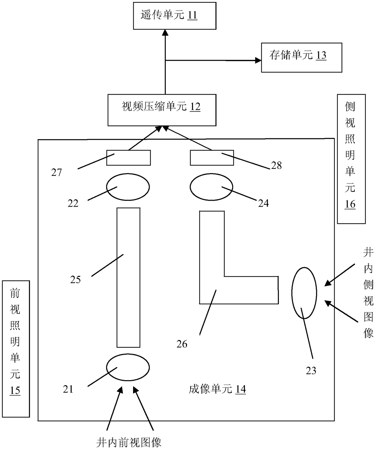
[0017] Such as figure 1 , figure 2 As shown, a downhole fiber optic imaging camera mainly includes a remote transmission unit 11, a video compression unit 12, a storage unit 13, an imaging unit 14, a front-view lighting unit 15, and a side-view lighting unit 16;

[0018] The output end of the imaging unit 14 is connected to the video compression unit 12, one end of the output end of the video compression unit 12 is connected to the remote transmission unit 11, and the other end is connected to the storage unit 13.

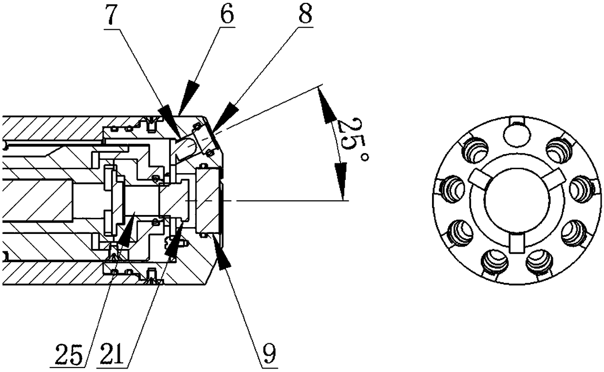
[0019] Front-view camera includes lens one 21, imaging fiber one 25, lens two 22, photosensitive chip one 27, side-view camera includes lens three 23, imaging fiber two 26, lens four 24, photosensitive chip two 28, lens one 21 and lens three The front ends of 23 are equipped with translucent sapphire glass resistant to high temperature and pressure.

[0020] The lighting unit includes a front-view lighting module and a side-view lighting module. The front-view lighting ...


PUM


Abstract

The invention relates to a downhole optical fiber imaging camera mainly comprising a remote transmission unit, a video compression unit, a storage unit, an imaging unit and a lighting unit, wherein the imaging unit comprises a front view camera and a side view camera, the two cameras have corresponding light sources, an in-well image is converged into an imaging optical fiber by a lens, the in-well image is restored on a photosensitive chip through the lens at the other end of the optical fiber, the photosensitive chip outputs a front view image and a side view image after performing digitization, a video compression module performs video compression on the images, the compressed video images are transmitted by the video compression unit to a ground system through a logging cable in the form of digitized images at a speed of two frames per second, and the digitized images are stored in the storage unit at a speed of 25-30 frames per second and are read out on the ground after the instrument is lift out from the wellhead. Due to the use of the imaging optical fiber, the photosensitive chip is away from a heating light source, which is conducive to improving the working temperature of the instrument, and moreover, the volume of the side view camera is further reduced, so that the instrument structure is further simplified.

Description

Technical field [0001] The invention relates to the technical field of petroleum and exploration, in particular to a storage type optical fiber imaging downhole camera instrument, which is applied in an open hole or a casing well. Background technique [0002] The existing downhole cameras mainly include the following two types: separate storage type downhole cameras, which cannot upload pictures, and cannot observe downhole conditions on the ground. Moreover, the design structure of the lighting module and the photosensitive chip together causes the working temperature of the instrument to deviate. Low, not suitable for operations in deep wells or in bad well conditions; downhole cameras using optical fiber cable transmission can upload videos in real time, but optical fiber cables are also required, and the downhole cost is high. The existing lighting unit shoots directly in front of the camera, which may cause reflection of particles in the front and the camera's light measure...

Claims


Application Information

Patent Timeline
Patent Type & Authority Applications(China)
IPC IPC(8): H04N5/225H04N7/18H04N7/22
CPCH04N7/183H04N7/22H04N23/45H04N23/55H04N23/56H04N23/54
Inventor 何峰江
Owner BEIJING JIEWEISITE TECH CO LTD
Why Eureka
Try Eureka