Eureka AIR delivers breakthrough ideas for toughest innovation challenges, trusted by R&D personnel around the world.

Backlight module and illuminated touch device thereof

A backlight module and touch device technology, applied in optics, light guides, optical components, etc., can solve the problems of inability to display virtual keys and visual images in partitions, afterimages, and misleading users, etc., to improve adjacent light interference and afterimages problem effect

Pending Publication Date: 2022-02-22
CHICONY POWER TECH CO LTD
View PDF0 Cites 0 Cited by
  • Summary
  • Abstract
  • Description
  • Claims
  • Application Information

AI Technical Summary

Problems solved by technology

[0004] However, the inventors have realized that a general light-emitting touch device only lights up all the light-emitting elements or extinguishes all the light-emitting elements, such as but not limited to: backlight lighting or side-lighting lighting, so as to light up the entire area of ​​the touch panel, However, it is still not possible to display virtual buttons and visual images in partitions
Even though each light-emitting element can be independently controlled to light up separately, there are still problems of adjacent light interference and afterimages, which cause afterimages to mislead users

Method used


Image

  • Backlight module and illuminated touch device thereof
  • Backlight module and illuminated touch device thereof
  • Backlight module and illuminated touch device thereof

Examples


Embodiment Construction

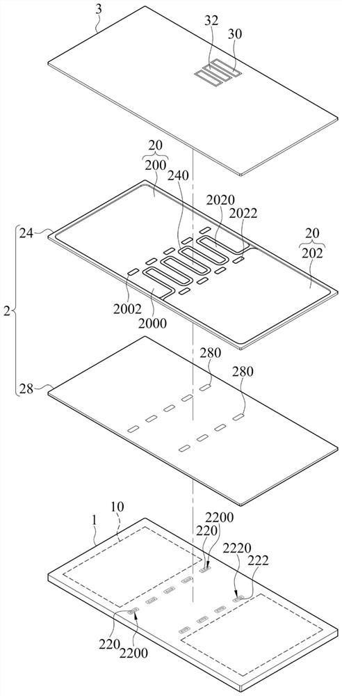
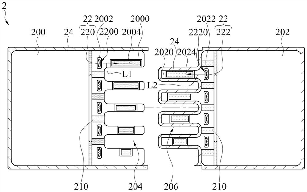
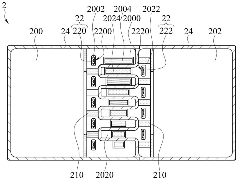
[0055] Various embodiments of the present invention will be described in detail below and illustrated with accompanying drawings. In the description of the specification, many specific details are provided in order to enable readers to have a more complete understanding of the present invention; however, the present invention may still be practiced under the premise of omitting some or all of the specific details. The same or similar elements will be denoted by the same or similar symbols in the drawings. It should be noted that the drawings are for illustrative purposes only, and do not represent the actual size or quantity of components, and some details may not be fully drawn for the sake of brevity of the drawings.

[0056] figure 1 It is a three-dimensional exploded schematic diagram of a light-emitting touch device according to an embodiment. figure 2 It is an exploded top view diagram of a backlight module according to an embodiment. image 3 It is a schematic top v...


PUM


Abstract

The invention provides a backlight module and an illuminated touch device thereof. The illuminated touch device includes a circuit board, a backlight module, and a cover plate. The backlight module includes a light guide plate, a light source assembly, and a light-shielding bar. The light guide plate includes a first plate body and a second plate body fitted with each other. The first plate body has a plurality of first microstructures, and the second plate body has a plurality of second microstructures. The light-shielding bar is at an outer periphery of the light guide plate and extends at an intersection between the first plate body and the second plate body, for blocking penetration of light between the first plate body and the second plate body. The cover plate includes first transparent regions and second transparent regions respectively corresponding to the first microstructures and the second microstructures.

Description

technical field [0001] The invention relates to a backlight module and a light-emitting touch device thereof, in particular to a backlight module suitable for partition display and a light-emitting touch device thereof. Background technique [0002] Traditional electronic products such as notebook computers usually have physical buttons and touch panels. With the development of thinner portable electronic products, the available space on the body is relatively reduced. Therefore, thin and light notebook computers may be on the touch panel. Displaying virtual keys and visual images saves physical key space and improves user convenience, that is, displays virtual keys and visual images on the touch panel through a backlight module for user operations. [0003] In a specific application scenario, the virtual buttons and visual images displayed by the light-emitting touch device may display, for example but not limited to, a computer function menu with segmented control, and dis...

Claims


Application Information

Patent Timeline
Patent Type & Authority Applications(China)
IPC IPC(8): G06F3/041G06F1/16G02B6/00
CPCG06F3/0416G06F1/1637G02B6/0078G02B6/005G06F3/03547G02B6/0088G02F1/133615G02B6/0036G06F3/041G02B6/0055G02B6/0066G02B6/0093G02B6/008G02F1/133606G02F1/133603G02F1/133607
Inventor 何宣纬黄俊铭
Owner CHICONY POWER TECH CO LTD
Why Eureka
Eureka Blog
Learn More