Switching device

A switch device and switch unit technology, which is applied in the direction of the power device and contact engagement inside the switch, can solve the problems of large operating force and impact force, large operating force, and asynchronous contact movement, and achieve the goal of operating force and impact The effect of small force, overcoming long power-on time, simple and reliable structure

Pending Publication Date: 2022-02-22
TIANJIN SVRUI INTELLIGENT ELECTRICAL CO LTD
View PDF13 Cites 0 Cited by
  • Summary
  • Abstract
  • Description
  • Claims
  • Application Information

AI Technical Summary

Problems solved by technology

[0004] like figure 2 As shown in the patent No. 201821456019.7, a commutation switch device is disclosed, which uses two short-time excitation electromagnet mechanisms to respectively drive a set of moving contacts and three sets of static contacts to switch on or off in forward and reverse directions to realize power commutation function, the three phases of power supply A, B, and C in this technical solution can only output one of them, and there is a problem that there are few power output terminals. The problem of high impact force and low lifespan
[0005] like image 3 As shown in the patent No. 201810727635.X, a dual-power automatic switching device is disclosed, which uses a bistable permanent magnet electromagnet to drive four groups of eight vacuum tube moving contacts and static contacts to switch on or off to realize power conversion. function, one electromagnet in this technical solution drives eight moving and static contacts to move simultaneously, which has the problems of large operating force and asynchronous contact movements, and also has the problem of high cost

Method used


Image

  • Switching device
  • Switching device
  • Switching device

Examples


no. 1 example

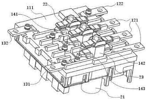
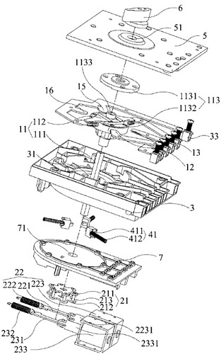
[0049] like Figure 4 to Figure 9 As shown, the present invention discloses a switch device 10, the switch device 10 includes a first switch unit 100, the first switch unit 100 includes an insulating casing 101, a first power inlet terminal 110A, a second power inlet terminal 110B, the first power outlet terminal 120, the second power outlet terminal 130, the first static contact 150A, the second static contact 150B and the first static contact 150A, the second static contact 150B between A moving contact 140, a bistable permanent magnet electromagnetic drive device 200, the first power supply inlet terminal 110A and the second power supply terminal 110B are respectively connected to the first static contact 150A and the second static contact The head 150B is electrically connected, and the moving contact 140 is connected to the first power outlet terminal 120 .

[0050] Please refer to Figure 4 , Figure 5 and Image 6 As shown, the first switch unit 100 also includes a ...

no. 2 example

[0067] Please refer to Figure 10 As shown, this embodiment introduces the internal structure of the switch unit of another switch device. In this embodiment, the drive shaft of the bistable permanent magnet electromagnet 210 is directly fixedly connected with the movable contact 140, and the drive shaft of the bistable permanent magnet electromagnet 210 is connected with the movable contact The angle between 140 is approximately 90 degrees, and the bistable permanent magnet electromagnet 210 drives the moving contact 140 to move linearly in both directions to connect with the first static contact 150A or the second static contact 150B. or disconnection, the internal action principle and external combination form of the switch device are consistent with those described in Embodiment 1, and will not be repeated here.

[0068] In the present invention, a bistable permanent magnet electromagnet is used to drive a movable contact and two static contacts to be connected or disconn...


PUM


Abstract

The invention discloses a switching device (10). The switching device (10) consists of at least two switching units, including a first switching unit (100), the first switching unit (100) comprises an insulating shell (101), a first power supply wire inlet end (110A), a second power supply wire inlet end (110B), a first power supply wire outlet end (120), a first static contact (150A), a second static contact (150B), and at least one moving contact (140) and at least one bistable permanent magnet electromagnetic driving device (200) which are arranged between the first static contact (150A) and the second static contact (150B), the moving contact (140) is bidirectionally driven by the bistable permanent magnet electromagnetic driving device (200) to be connected or disconnected with the first static contact (150A) or the second static contact (150B) respectively; and on the moving plane of the moving contact (140), the included angle between the driving shaft of the bistable permanent magnet electromagnetic driving device (200) and the moving contact (140) ranges from 30 degrees to 150 degrees.

Description

technical field [0001] The invention relates to the field of electrical appliances, in particular to a switch device. Background technique [0002] In the low-voltage and medium-high voltage electrical appliance industry, electromagnetic mechanisms are widely used in various switchgears due to their advantages of fast action speed, long life and low cost. The driving components of electromagnetic mechanisms are electromagnets. Electromagnets mainly have two typical mechanisms. , one is a long-term or short-term current excitation mechanism, and the other is a permanent magnet mechanism. [0003] like figure 1 As shown in the patent No. 201610916682.X, a commutation switch device is disclosed, which uses three permanent magnet mechanisms to respectively drive three sets of dynamic and static contacts to connect or break, and one of the permanent magnet mechanisms drives a set of dynamic and static contacts. On or off to realize the function of power commutation. The three p...

Claims


Application Information

Patent Timeline
Patent Type & Authority Applications(China)
IPC IPC(8): H01H3/28H01H1/12
CPCH01H3/28H01H1/12
Inventor 沈迪南寅王文涛任庆庆施谦何斌刘万里董郁
Owner TIANJIN SVRUI INTELLIGENT ELECTRICAL CO LTD
Why Eureka
Try Eureka